HOW TO: Extend Breathers (on a KK Liberty)
This thread is intended as a “how to” for extending the various breather lines up higher on the KK Liberty. This covers extending 4 breather lines:
1. Rear Differential
2. Front Differential
3. Transfer Case
4. Transmission (note, I’ve got the automatic transmission and have no idea how the manual transmission may differ)
Extending the breather lines upward helps protect your vehicle during water crossings from the likelihood of water entering these vital components which are dependent upon proper and consistent lubrication of drive train components. Don’t have any illusions about “waterproofing” your KK – this mod is to just help protect your investment better during water crossings appropriate for your vehicle and skill level. For more discussion on this topic, see
this thread,
this thread or
this thread. Big thanks to the LOST KJ members for identifying how this mod could be done on their Libertys -- I referenced this info while performing this mod on my KK. This is a pretty cheap modification, yet helps protect expensive parts of your KK. If you
ever think you’ll cross any water with your KK, there is no reason not to perform this mod.
Duration
Although it took me about 5 hours, including lunch and 5 trips to get supplies, I hope by generating this “how to” that anyone else can start out with all the necessary supplies and tools and be able to perform this KK mod in 1.5-3 hours. This is a pretty easy modification and provides a good amount of additional protection.
Tools Required
a. (Optional) Fender cover(s). If you're not going to use fender covers but aren't ready to scratch up your Liberty's fenders, then at least untuck your shirt (if it isn't already) and let it hang over your belt buckle.
b. Safety glasses – I recommend always wearing safety glasses whenever working under a vehicle and/or with any tool that may create objects flying through the air
c. Jack stands
d. Good flashlight or drop light
e. Side cutters / hose cutter / box knife to cut new hose to length
f. Side cutters also used for cutting cable/zip ties
g. Small flat bladed screwdriver and/or small ice pick for loosening fittings from existing hose ends
h. Small screwdriver or nut driver for use on the small hose clamps
Parts Required
a. 5/16” SAE hose x (at least) 11’-0” long (will be cut to length later as required)

b. (10-20) 8” long plastic cable/zip ties
c. (3) 5/16” hose in-line union (barbed) fittings (plastic is fine in my opinion for this application)
d. (6-10) small hose clamps (for 1/4” – 5/8” OD hose)
e. (3) Coated Tubing B-Clamps for 1/2” or 9/16” OD Hose (found with plumbing supplies in home improvement stores) as shown below:

f. (1) M8x1.25 Locking Nut (I used a nylon insert hex nut)
g. (1) M8 SAE Flat Washer (the smaller OD washer, not the larger diameter flat or fender washer)
h. (2) M6x1.0 Locking Nuts (I used nylon insert hex nuts)
i. (2) M6 Fender Washers (larger OD washers)
These supplies should cost about $20 or so.
Step Summary
REAR DIFFERENTIAL:
Step 1: Locate and Remove Rear Differential Breather
Step 2: Prep Replacement Rear Differential Breather
Step 3: Install the Upper End of the Rear Differential New Breather Line
Step 4: Route and Install Rest of the Rear Differential New Breather Line
FRONT DIFFERENTIAL:
Step 5: Locate and Remove Front Differential Breather
Step 6: Extend Front Differential Breather
Step 7: Route and Install Upper End of the Front Differential New Breather Line
TRANSFER CASE & TRANMISSION:
Step 8: Locate and Remove Transfer Case & Transmission Breathers
Step 9: Route and Install the Upper End of the Transfer Case New Breather Line
Step 10: Route and Install the Upper End of the Transmission New Breather Line
Step 11: Fine Tune and Install Upper Ends of Both New Breathers
Step 12: Completion Within Engine Compartment
STEPS:
Step 1: (Rear Diff) Locate and Remove Rear Differential Breather
On a hard and level surface, jack up the rear of the vehicle on jackstands, chock the front wheels and insure the vehicle is stable. Follow all appropriate safety precautions before working under an elevated vehicle.
The Rear Differential breather tube is on top of the driver’s side of the rear axle as shown below:

Which then runs up onto the left-right cross member as shown below (looking upward at the bottom of the vehicle):

In the above, you can see the little white breather cap at the end of the breather line. As you can see, this breather cap isn’t really that high in elevation. Of all 4 of the breathers in this “how to”, this is the one that is the lowest and thus at the greatest risk of water getting into a vital drive-train component.
Now, remove the Rear Differential breather tube in its entirety. Pull it up off the rear axle. Open the clip holding it to the left-right cross member:
 Step 2: (Rear Diff) Prep Replacement Rear Differential Breather
Remove the little white breather end fitting from the OEM breather tube. Be careful not to break the little cap that bobbles around. Remove the end fitting just by working it back and forth and pulling it out of the hose. If needed, carefully insert a small flat-bladed screwdriver or ice pick type tool into the hose alongside the fitting to loosen the hose around the fitting.

Install the breather end fitting into approximately 5’-0” of the new 5/16” SAE hose. If you have more than 2.5” of lift, you may want to start out with an even longer piece of hose.
Step 3: (Rear Diff) Install the Upper End of the Rear Differential New Breather Line
Looking upward into the gas fill tube cavity from below, you can see the area where the new rear differential breather is going to be routed:

Install the breather cap end of the new breather line up within the gas fill tube cavity by cable-tying it in multiple locations to the gas filler tube. Insure the new breather vent cap is not bound against anything so it can freely bobble around. In the photo below, you can see the new Rear Differential breather line and cap installed up within the gas filler tube area and cable tied to the gas filler tube (looking up from below):
 Step 4: (Rear Diff) Route and Install Rest of the Rear Differential New Breather Line
Now that the upper end of the new breather line for the Rear Differential is installed and secured, route the new breather hose and secure it with cable ties to the gas filler tube. Insure to keep the breather line away from the rear shock.

Keep the new Rear Differential breather hose on the side of the gas filler tube closest to the inside/centerline of the vehicle. Insure you keep the breather hose away from any metal or sharp edges that may cut or abrade it over time from vehicle motion or rear axle flexing.

Remember, before you cut the hose to length and install it back onto the top of the rear axle, you’ll want enough slack to accommodate the amount of axle drop your KK is configured for. Try positioning the slack so it isn’t likely to catch on anything else. Test move the point where you plan to cut it to match up with the rear axle connection down and back to confirm its clearances and movement.

Once you’re comfortable with how much breather hose you need, cut it at your desired location. For me (with my JBA 2.5” Lift), I cut 4” off so I wound up using 4’-8” total length of new hose for my Rear Differential breather. After the hose is cut, then reinstall it on the connection on top of the rear axle. The hose connection to the rear axle seems tight and the OEM connection was bare, so it is up to you if you feel you should add a small hose clamp around the hose.

This raises the breather cap for the Rear Differential approximately 18”. Once satisfied with all work for this extended breather, then lower the vehicle back to the ground.
Step 5: (Front Diff) Locate and Remove Front Differential Breather
FYI, here’s where the Front Differential breather hose starts (looking up from below the vehicle):

But we’re not going to have to mess with the breather lines that are under the vehicle. Instead, go to and open the engine compartment. The Front Differential breather tube comes up into the engine compartment and is attached via an integral mounting bracket just below the battery tray:

Pry the Front Differential breather tube integral mounting bracket up off its stud with a flat-bladed screw driver and by wiggling it back and forth.
Step 6: (Front Diff) Extend Front Differential Breather
Now that the existing Front Differential breather is loose within the engine compartment, move it upward to get it as high as possible to provide more clearance for working on it. Remove the black end fitting with integral breather and mounting clip from the end of the OEM tube. Again, if needed, carefully insert a small flat-bladed screwdriver or ice pick type tool into the hose alongside the fitting to loosen the hose around the fitting.
Install (1) 5/16” in-line union fitting and (2) hose clamps onto an end of approximately 2’-6” of the new 5/16” SAE hose. No need to tighten the hose clamps yet.

Then install the other end of the in-line union fitting into the now open end of the existing Front Differential breather tube (where the old breather/mounting end fitting used to be). Slide (1) of the hose clamps over the union and onto the existing hose side of the union and tighten it. Tighten the other hose clamp on the new hose side of the union.
Then secure the now-extended Front Differential breather hose along the outside of the metal rail heading from the front of the engine to toward the firewall at the back of the engine. The photo below also shows the in-line union in the hose.

Cable tie the new breather hose in multiple locations as necessary to secure it.
Step 7: (Front Diff) Route and Install Upper End of the Front Differential New Breather Line
Route the new Front Differential breather extension line back to and up the firewall toward the grounding strap mounting location. Insure you have the breather hose reasonably loose and without any kink or pinch points.
Slip (1) of the coated tubing B-clamps over the open end of the new breather extension hose up by the firewall. Position it so the Front Differential breather hose extension will be routed as shown below:

Identify good positioning for reinstalling the breather cap with integral mounting bracket and cut the hose at the desired location. For me, I cut 4” off so I wound up using 2’-2” total length of new hose for extending my Front Differential breather. After the hose is cut, then reinstall the original end fitting with breather cap and integral mounting bracket. Position as shown in the photo above and insure the breather cap is free to bobble around.
Secure the coated B-clamp to the larger and open stud sticking out of the firewall near the grounding strap mount. Secure the coated B-clamp with the (1) M8 SAE flat washer and then (1) M8x1.25 locking nut. This raises the Front Differential breather approximately 13”-14”.
Step 8: (Xfr Case & Tranny) Locate and Remove Transfer Case & Transmission Breathers
FYI, here’s where the Transfer Case breather hose starts (looking up from below the vehicle):

I couldn’t ever find the origination of the (automatic) Transmission breather hose. Fortunately, we’re not going to have to mess with either of these breather lines from under the vehicle. Instead, go back to the open engine compartment. Both the Transfer Case and (automatic) Transmission breathers come up behind the engine at the fire wall and mount off the transmission “dipstick” tube. As shown below, the (automatic) Transmission breather cap is pink and closest to the passenger side while the Transfer Case breather cap is white and closest to the driver’s side:

Remove both breathers off the mounting to the transmission dipstick tube.
Step 9: (Xfr Case) Route and Install the Upper End of the Transfer Case New Breather Line
Pull the Transfer Case breather tube toward the driver’s side to get more slack for working on extending it:

For the Transfer Case breather tube, remove the white breather end fitting from the OEM breather tube. Be careful not to break the little cap that bobbles around. Remove the end fitting as with the other breather fittings.
Install (1) 5/16” in-line union fitting and (2) hose clamps onto an end of approximately 1’-6” of the new 5/16” SAE hose. Again, no need to tighten the hose clamps yet.
Then install the other end of the in-line union fitting into the now open end of the existing Transfer Case breather tube (where the old breather end fitting used to be). Slide (1) of the hose clamps over the union and onto the existing hose side of the union and tighten it. Tighten the other hose clamp on the new hose slide of the union.
Move the Transfer Case breather hose back toward its original position. Route it up along the firewall, behind the metal bar and toward the open stud sticking out of the firewall. Insure you have the breather hose reasonably loose and without any kink or pinch point.
Slip (1) of the coated tubing B-clamps over the open end of the Transfer Case new breather extension hose up by the firewall. Position it so the Transfer Case breather hose extension will be approximately as shown below:

Do
not secure the B-clamp nor cut the hose for the Transfer Case breather extension at this time.
Step 10: (Tranny) Route and Install the Upper End of the (Automatic) Transmission New Breather Line
For the (automatic) Transmission breather tube, remove the pink breather end fitting from the OEM breather tube. Be careful not to break the little cap that bobbles around. Remove the end fitting as with the other breather fittings.
As with before, install (1) 5/16” in-line union fitting and (2) hose clamps onto an end of approximately 2’-0” of the new 5/16” SAE hose. Again, no need to tighten the hose clamps yet.
Then install the other end of the in-line union fitting into the now open end of the existing (automatic) Transmission breather tube (where the old breather end fitting used to be). Slide (1) of the hose clamps over the union and onto the existing hose side of the union and tighten it. Tighten the other hose clamp on the new hose slide of the union. This is the hardest union and hose extension to install due to tight physical constraints.
Move the (automatic) Transmission breather hose back toward its original position. Route it up along the firewall, behind the metal bar and on the passenger side of the extended Transfer Case breather hose just installed and toward the open stud sticking out of the firewall closest to the passenger side. Insure you have the breather hose reasonably loose and without any kink or pinch points.
Slip (1) of the coated tubing B-clamps over the open end of the (automatic) Transmission new breather extension hose up by the firewall. Position it so the (automatic) Transmission breather hose extension will be approximately as shown below:

Do
not secure the B-clamp nor cut the hose for the (automatic) Transmission breather extension at this time.
Step 11: (Xfr Case & Tranny) Fine Tune and Install Upper Ends of Both New Breathers
Fine tune positioning of both the Transfer Case breather extension and the (automatic) Transmission breather extension relative to each other and surrounding components. Once satisfied, identify good positioning for reinstalling the breather cap on each breather extension and cut the appropriate hose at the desired location. Insure each breather end cap will be unobstructed. I cut mine so the coated B-clamp went around the hose right at the end fitting. For me, I cut 6” off the Transfer Case breather extension hose so I wound up using 1’-0” total length for it and I cut 3” off the (automatic) Transmission breather extension hose so I wound up using 1’-9” total length for it. After the hose is cut, then reinstall the original end fitting with breather cap on the appropriate hose (pink to the Transmission breather closest to the passenger side and white to the Transfer Case breather closest to the center of the engine compartment). Position as shown in the photo below and insure each breather cap is free to bobble around.

Secure each of the (2) coated B-clamps to the small and open studs sticking out of the firewall with (1) M6 fender washer and then (1) M6x1.0 locking nut.
This raises both the Transfer Case and (automatic) Transmission breathers approximately 12” higher.
 Step 12: Completion Within Engine Compartment
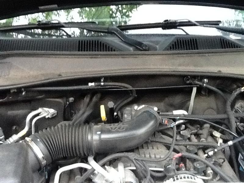
Now with all (3) breathers within the engine compartment raised, it should look like this:

Congratulations, you’re done!