The readings that layback40 got were pretty standard, and can be portrayed as readings taken from the larger C1 connector of the ECM. Disconnect the battery, then disconnect the ECM connector. Stick straight pins (be gentle) in the ECM connector holes to touch the actual pins. Use an Ohm meter to take resistance / continuity measurements. If the wires are twisted tightly together at any connector, they could be shorted or broken.
To correct my mistake from earlier posts: I referred to the ECM connectors as P1 (large) and P2 (small); they are really C1 and C2. I'll get the stick and wait out behind the shed.
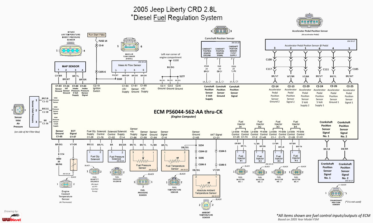
 ECM Power and Ground
Measure continuity from ECM C2 pin 19 to Power Control Center Fuse 14 ~0 ohms
Measure continuity from ECM C2 pin 2 to chassis ground, C2 pin 4 to chassis ground, C2 pin 6 to chassis ground ~0 ohms
Fuel Pressure Control Solenoid ( one at the back of rail ) ~ 3 to 5 ohms
ECM C1 pins 52 and 4. Should read the same from 4 to 52 also.
If reading is 1 ohm or less, then suspect a short in the solenoid or wiring. Disconnect solenoid and measure again.
If reading is greater than 1000 ohms (1K ohm) then suspect a broken wire.
Measure continuity through the wires from ECM C1 pin 4 to ground, pin 52 to ground ~ open circuit
(Fuel Quantity Solenoid = Fuel Quality Solenoid = Fuel Regulator Solenoid)
Fuel Quantity Solenoid ( on CP3 High Pressure Fuel Pump ) ~ 3 to 5 ohms
ECM C1 pins 28 and 76. Should read the same from 76 to 28 also.
If reading is 1 ohm or less, then suspect a short in the solenoid or wiring. Disconnect solenoid and measure again.
If reading is greater than 1000 ohms (1K ohm) then suspect a broken wire.
Measure continuity through the wires from ECM C1 pin 28 to FQS pin 1 ~ less than 1 ohm
Measure continuity through the wires from ECM C1 pin 76 to FQS pin 2 ~ less than 1 ohm
Measure continuity through the wires from ECM C1 pin 28 to 76 ~ open circuit
Measure continuity through the wires from ECM C1 pin 28 to ground, 76 to ground ~ open circuit
Fuel Pressure Sensor ( on Fuel Rail ) This is a solid state device shat should be tested for voltages while the engine is running.
Measure continuity through the wires from the ECM connector pins to the Fuel Pressure Sensor connector pins
ECM C1 pin 84 to
Fuel
Pressure
Sensor pin 1 ~ less than 1 ohm
ECM C1 pin 59 to FPS pin 2 ~ less than 1 ohm
ECM C1 pin 86 to FPS pin 3 ~ less than 1 ohm
Measure continuity through the wires from ECM C1 pin 84 to 59, and 84 to 86, and 86 to 59 ~ open circuit
Measure continuity through the wires from ECM C1 pin 84 to ground, 59 to ground, 86 to ground ~ open circuit
Set up to measure voltages: Insert straight pins alongside wires into Fuel Pressure Sensor connector pins 1, 2, 3. Ensure no shorts.
Reconnect all connectors, then reconnect the battery.
Measure voltages of pin 1 (+) to pin 3 (-): Key off ~0vdc. Key on ~5vdc steady. Engine start ~5vdc steady
Measure voltages of pin 2 (+) to pin 3 (-): Key off ~0vdc. Key on ~0.5vdc. Engine start = ~1.5vdc to ~3.5vdc varies with RPM
Dean.


 Read the codes and got the explanations: P0090, P0403, P1140.