Hi All,
I wanted to add a
second power outlet to the dash in my KK, because having a single outlet was frustrating when I wanted to run my GPS and charge my phone or iPod. I know you can buy splitters for power outlets, but they're ugly and take up a lot of room. I have other accessories that need to be hardwired, including a CB radio. I was already frustrated by all the extra wiring coming from my Jeep's battery, so I decided to clean it all up by adding an
auxiliary fuse panel under the dash at the same time as adding a second power outlet. All the accessories will now tap into 12V power at the fuse panel, rather than having each one either spliced in to existing lines or hardwired to the battery. I figured a write-up would help someone else, so here you go!
Disclaimer:I am an ecologist, not an electrician. Modding my Jeep is a fun hobby. Therefore, I make no guarantees about this writeup and you voluntarily assume the risks of modding your vehicle's electrical system if you follow (or don't follow) these instructions. Read on and mod at your own risk!
Here is my wiring diagram. I'm sure I could make this drawing a little better by "untangling" some of the wires, but hopefully it's clear enough. Clicking on it gets you a larger image.
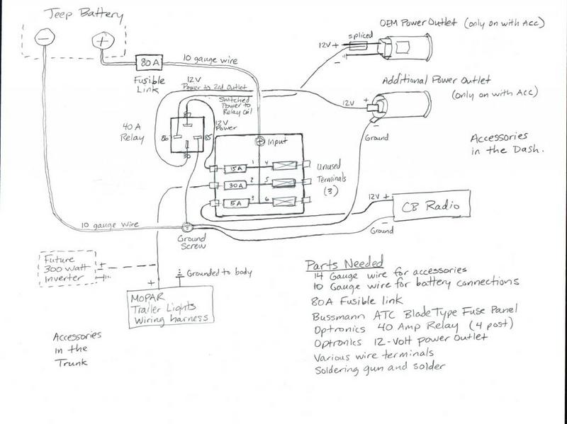
Now that you understand the method behind my madness, let's get on with the installation!
1) Buy and/or collect the components you need.All parts came from the local auto parts store and what I had on hand. I think I was able to do everything for approximately 50 bucks, and the install took me about 4-5 hours.
* Optronics 12-Volt power outlet
* Optronics 40 Amp Relay (to switch the power outlet on only when the ignition is in the ACC or ON position)
* Bussmann ATC fuse panel with 6 circuits (small enough for my purposes and still relatively inexpensive)
* 10 gauge wire for the direct lines from the fuse panel to the battery
* 80 Amp Fusible Link (to wire in-line between the battery and fuse panel)
* 14 gauge wire to connect the accessories to the fuse panel
* Various wire terminal connectors (bought a set)
* Various ATC fuses (bought a set)
* Various machine screws with washers and nuts (bought a set)
* 3 metal corner L-brackets to hold fuse panel (I had these from a previous home project)
* Soldering gun and solder, wire strippers, drill, and various hand tools
* Multimeter for testing for electrical current (and to determine that you wired everything up correctly)
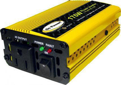
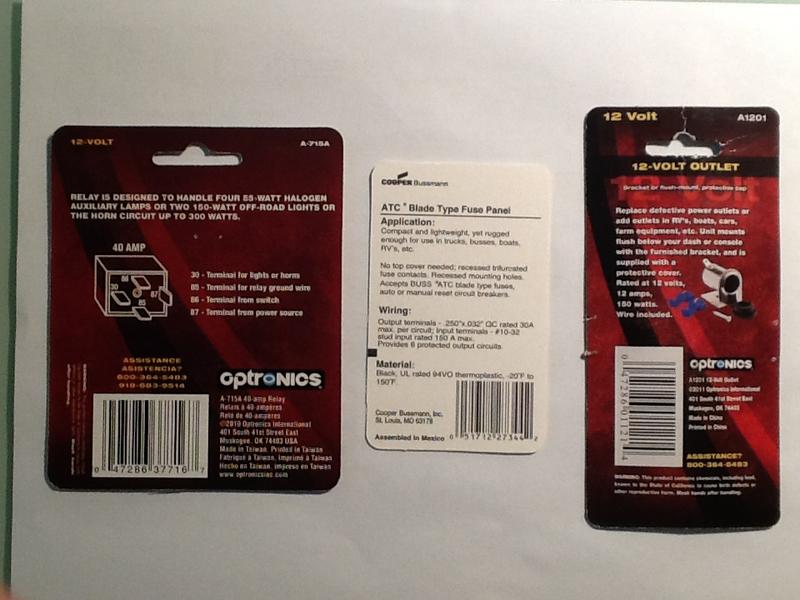
Here'a a photo of the three major electrical parts to buy:
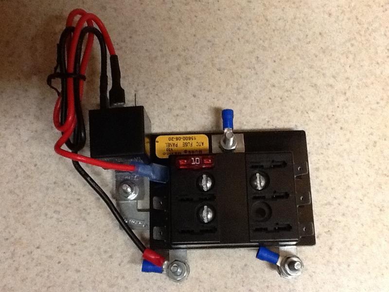
 2) Assemble your fuse panel components.
 Here's a photo of the auxiliary fuse panel put together, but not yet installed in the Jeep. I attached 3 metal L-brackets to the back of the fuse panel using machine screws. These metal brackets provided the support for the fuse panel, 40-Amp relay, and ground screw. They will be used to fasten the fuse panel to the Jeep.
The relay is optional if you don't care that your new power outlet will be on all the time. But if you'd like to have the power outlet on a switch, or to come on only when the Jeep is running (which was my plan), you'll need it. The directions for how to wire up the relay are printed on the back of the relay's packaging, which is in the previous photo.
3) Before doing any wiring in the Jeep, be sure to disconnect the negative terminal from the battery.
This will prevent unpleasant surprises (electrical shocks or blown electrical components).
4) Engine Compartment Side:We are going to run 10-gauge wires from the battery connectors through the rubber grommet in the firewall into the area behind the steering wheel.
a) The knee panel under the steering wheel opens like the glove box, but you'll need to give it a good tug from the top to get it to release. Don't worry, it won't break. Once it's in the down position, you can slide it to the left to disengage and remove it.
b) Locate the circular rubber grommet/plug in the firewall. Push it out towards the engine compartment. Once it pops out, drill two holes in it for your main power wires.
c) Measure 2 lengths of 10 gauge wire to span the distance from the front of the battery, through that hole in the firewall, to your steering wheel. I used yellow wire for the + (hot) and black wire for the - (ground). Thread the wires through the 2 holes you just drilled in the rubber grommet, and then reinstall that back into the firewall.
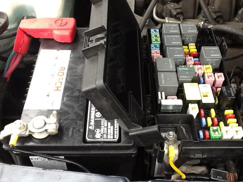
d) On the engine compartment side, crimp and solder an "O" connector to the end of the black (ground) and attach that to the - battery terminal screw (still disconnected from the battery of course).
e) Cut a 4 inch length off the end of the yellow wire. Attach an "O" connector to both ends of the short piece. One end will attach to the + battery terminal (I used the hot + screw inside the Jeep's main fuse box).
f) Attach an "O" connector to the end of the yellow wire that goes thru the firewall.
g) Connect the two yellow wires to each end of the 80 Amp Fusible Link. Tape over the connection on either side so that no metal is exposed. Using a fusible link is an important safety precaution because it prevents your fuse panel and the accessories connected to it from drawing too much current and starting a fire in your rig. You can use different fusible link amperages depending on your needs. The Bussmann fuse panel is rated at 150 Amps for the + input screw, so that would be the maximum amps you'd want coming from the battery (even though each of the 6 individual circuits is rated for 30 Amps). I only plan on having 50 Amps of accessories max, so I thought 80 Amp fusible link would be a good safeguard.
Once everything is assembled under the hood, it should look like this (but the - battery terminal should still be disconnected from the battery). Note the Fusible Link attached to the yellow wire in the lower right of the photo:
 5) Under the Dash:
We are going to wire up the fuse panel and then install it to the black metal bracket located under and to the left of the steering wheel.
a) Attach "O" connectors to the ends of the yellow (+) and black (ground) wires.
b) The yellow wire can be attached to the + input screw on the fuse panel body.
c) The black wire can be connected to one of the screws we will use to mount the fuse panel, via the L-brackets, to the black metal bracket under the steering wheel.
d) For accessories that will have power all the time: Connect the + power wire from the accessory to an open blade on the fuse panel, and connect the - ground wire from the accessory to the common ground screw. Then install the correct amperage fuse.
e) For the accessory that will use the relay (a.k.a. my new power outlet):
* Connect the blade on the fuse panel to the 87 post on the relay using a short wire.
* Connect a short wire from the 85 post on the relay to the common ground screw.
* Cut 3 sections of 14 gauge wire to span the distance from the relay to the center dash area where the power outlet will be. Be sure to leave a little extra slack. I use red wire for + (hot) and black for - (ground).
* Connect the red + power wire for the power outlet to the 30 post on the relay.
* Connect the black - ground wire from the power outlet to the common ground screw.
* Connect the on/off switch wire to the 86 post on the relay. This wire will be used to trigger the relay "on" only when the OEM power outlet is getting power (i.e., when the Jeep is running). Alternatively, you could hook it up to a manual switch.
* Install the correct amperage fuse for the power outlet.
f) Fasten the fuse panel to the black metal bracket under the steering wheel, where it will be mounted permanently. I put foam weather stripping between the black metal surface and the fuse panel to prevent rattling. In the process of installing the panel to the black metal mounting surface, I hooked up all the grounds to the ground screw.
Here's a photo of everything wired up and installed:
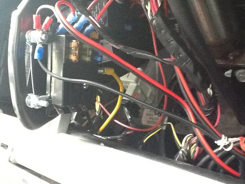
Note the 10 gauge yellow + power wire connecting to the back of the fuse panel, and the common ground screw. The 10 gauge - black ground wire is attached to this screw, but on the other side of the mounting surface where you can't see it. There are 1 relay ground and 2 accessory ground wires attached to the screw. You can see the three fuses for the circuits that are in use, with the three blue wire connectors attached to the top of the fuse panel.
6) Installing the power outlet in the center dash panel:a) Remove the center trim panel around the radio by carefully lifting the gray tabs on either side of the top while prying the center of the top towards you with a trim removal tool or other flat tool (a large screwdriver will do, but be careful not to scratch the plastic). There are fasteners on the back that will release, 2 or 3 on each side. Once the panel has released enough to tilt towards you, pull it up to release the two bottom clips. Getting this panel off the first time was a little tricky, but it gets easier.
b) Carefully release the wiring harnesses from the center panel by reaching behind it. On my Sport model there were two wiring harnesses for the climate controls, one for the bottom button bar, and one for the OEM power outlet. They all release differently, but you will have to press/pinch on a clip while pulling the harness out of the socket. The largest harness on the climate controls has a red tab that must be pushed forward (towards the front of the Jeep) before you can release it. There may be more wiring harnesses if you have a fancy model with lots of options. I have a Sport. Once all wires are released, you can get the center trim panel out of the way. Set it aside for now.
c) Run your three wires for the new power outlet from under the steering wheel, between the panels to the lower center dash area. Be careful not to have them interfere with the operation of the brake pedal, clutch, or anything else that moves under there.
d) Locate the wiring harness for the OEM power outlet. The pink wire was the + (hot) on mine, and the black was the - (ground). If you're not sure, you can briefly connect your battery, turn your key to the "acc" position, and check the terminals with a multimeter. If you do, be sure to disconnect the battery before proceeding.
e) Splice the on/off switch wire (running to the 86 terminal on your relay) to the pink + (hot) wire going into the OEM power outlet. (When you turn the Jeep on, the OEM power outlet will get power, and this wire will tell the relay to turn on the power to the second power outlet.) If you have a multimeter, you should be able to test that it works properly by checking whether the new circuit is live only when the key is on. Alternatively, you should hear the relay "click" on when you turn the key to "acc".
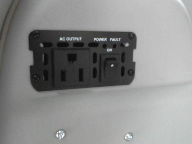
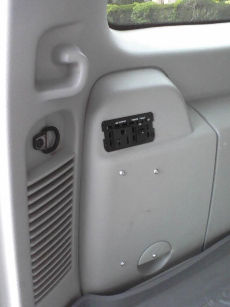
f) Next, you need to drill the hole for the new power out outlet in the center trim panel. Measure two or three times to make sure you have it right before drilling, as there is no going back! The position of the hole will not be exactly the mirror image of the OEM outlet because the wall inside the center dash area is thicker on the left than it is on the right. Your new power outlet will be slightly closer to the central button bar than the OEM outlet is. I drilled it out by first using a very small drill bit to begin the center of the hole, then enlarging the hole using a step bit. The step bit will guarantee that your final hole is perfectly round. Install the new power outlet onto the center panel and make sure it is secure.
g) Connect the red + wire to the central terminal on the new power outlet and the black - wire to the terminal on the metal housing.
h) Position the center dash bezel in place, reach behind it to connect all your wiring harnesses, and snap it back into place.
i) Reinstall and close the knee panel beneath the steering wheel.
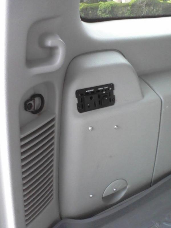
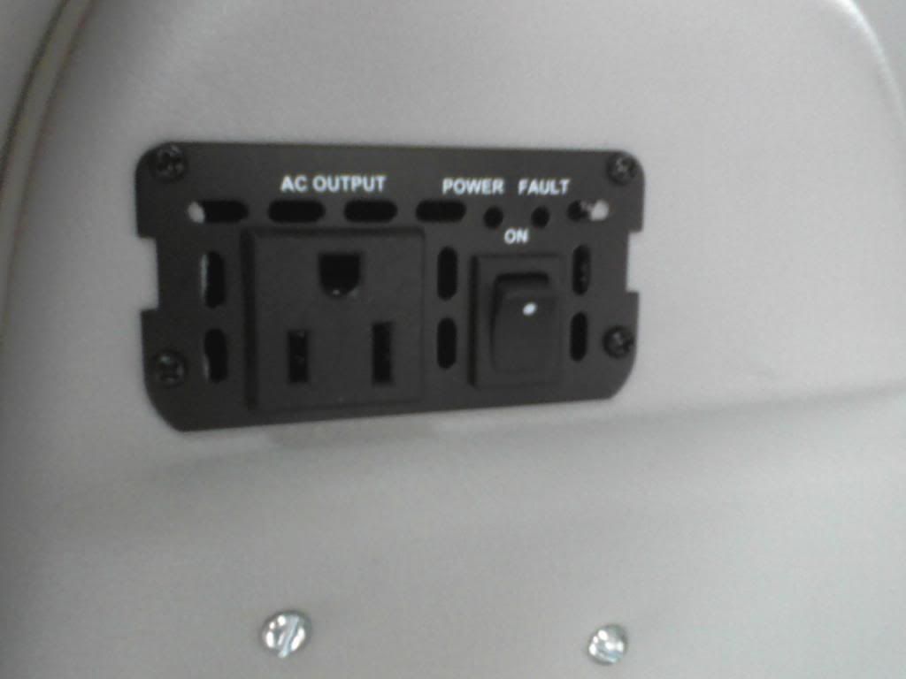
Here is the only evidence of all your hard work that actually shows:
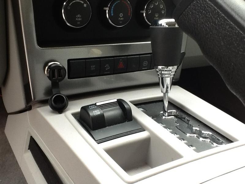
I have a USB charger in the socket.
7) Reconnect and torque down your battery terminal connectors. Close the main fuse box in the engine compartment and close the hood.
8) Test the system: Plug something into the new power outlet. It should be off if the Jeep is off. Turn the key to ACC or ON. The accessory in the new power outlet should turn on. Make sure all your other accessories work properly as well, and test the OEM power outlet too, just to make sure it still works. You're done!
What to expect, and a note of caution: I designed the wiring of this mod so that the 2nd power outlet does NOT draw power from this same circuit as the OEM outlet (leading to overloading and blown fuses), but instead it draws power directly from the battery and has its own fuse. The 20 Amp M7 fuse in the KK's main fuse box is for the Jeep's OEM power outlet. It has 2 positions, one that allows the power outlet to be hot all the time, and the other to send power only when the key is in the ACC or ON position. I keep mine in the ACC/ON position. Because of the relay, the 2nd power outlet will mirror the behavior of the OEM outlet. So, if the M7 fuse is in the "on all the time" position, the new power outlet will be on all the time. If the M7 fuse is set to the ACC/ON position, the second power outlet will behave the same way. Here's the potential issue: If you set the M7 fuse to "on all the time," the relay will always be drawing a small amount of power, even when the Jeep is off. The relay's electromagnet only uses something like 0.3 Amps, but this could potentially draw down the battery after a long time. With the M7 fuse in the "ACC/ON" position, the relay will not draw any power when the Jeep is off. If you want your power outlet to be hot all the time, just eliminate the relay from the above setup and simply wire the new power outlet directly to an open circuit on the auxiliary fuse panel.