I found this related specifically to the 2.8L CRD:
Quote:
FUEL INJECTION PUMP
DESCRIPTION
A radial, 3 piston pump with a gear type fuel pump
attached to the back, is used as the high pressure
pump for fuel pressure generation (Refer to 14 - FUEL
SYSTEM - WARNING).
The pump is driven by the timing belt. Pressure is
generated independently of the injection process. The
pump is lubricated with diesel fuel and is not responsible
for fuel injection timing.
OPERATION
Cascade Overflow Valve
Instead of using an electric supply pump, this fuel system uses a gear supply pump located inside the rear of the
high pressure pump. The pump is driven by an eccentric on the end of the high pressure pump shaft. The gear
pump draws fuel from the fuel tank through the fuel filter.
The pressurized outlet side of the gear pump provides pressurized fuel to a branched circuit internal to the high
pressure pump flange, which supples both the fuel quantity solenoid and the cascade overflow valve. Because the
gear pump increases fuel flow and pressure as the engine rpm increases, the pressure is regulated by the cascade
overflow valve. The cascade overflow valve and gear supply pump are not serviced independently of the high pressure
pump.
The cascade overflow valve has two functions:
² Regulation of lubrication fuel to the internal moving parts of the high pressure pump
² Regulation of the fuel pressure being supplied to the fuel quantity solenoid
The cascade valve has a machined center piece that has three drillings. One for overflow, one for lubrication and
one for supply. The valve works in three stages based on the pressure entering the inlet of the valve.
Stage 1
When the fuel pressure entering the tip of the cascade valve is between 0 and 3 bar (44 psi), the spring force is not
overcome and fuel only flows through the center drilling. This drilling always allows fuel flow through to the pump
center ring and lubricates the pump bushings and internal moving parts. This circuit also allows air to bleed during
initial cranking and returns the air to the fuel tank. The cascade valve is only in stage one during cranking.
Stage 2
When the fuel entering the cascade valve exceeds 3 bar (44 psi), but is less than 5 bar (73 psi), the center piece
of the valve moves against the spring force aligning another passage for lubrication purposes. Stage 2 can be
reached during cranking and initial start up.
14 - 54 FUEL DELIVERY - 2.8L DIESEL KJ
Stage 3
When fuel pressure exceeds 5 bar (73 psi), the center of the valve aligns with the overflow passage. This stage
relieves the pressure into an overflow circuit that sends the fuel back to the inlet side of the gear pump which limits
maximum fuel pressure to 5 bar (73 psi). Lubrication fuel also continues to flow though the other ports during this
stage. Excess is sent back to the fuel tank through the return circuit.
High Pressure Pumping Plungers
The fuel quantity solenoid supples three high pressure pumping chambers. The pumping chambers have one way
inlet valves that allow fuel to flow into the chambers. The valves then close during compression of the fuel and
cause the high pressure fuel to overcome a ball and angled seat outlet valve.
All three pumping chambers are tied together in one circuit internal to the pump and provide high pressure fuel up
to 1600 bar (23,000 psi) through a steel line, to the fuel rail.
The pump is driven at 1:1 engine speed and is not responsible for injection timing. The pump is only responsible for
providing high pressure fuel while the ECM controls the injection timing.
REMOVAL
WARNING: High - pressure lines deliver diesel fuel under extreme pressure from the injection pump to the
fuel injectors. This may be as high as 1600 bar (23,200 psi.). Use extreme caution when inspecting for high
- pressure fuel leaks. Fuel under this amount of pressure can penetrate skin causing personal injury or
death. Inspect for high - pressure fuel leaks with a sheet of cardboard. Wear safety goggles and adequate
protective clothing when servicing fuel system.
1. Disconnect negative battery cable.
2. Remove engine cover and bracket (Refer to 9 -
ENGINE - REMOVAL).
3. Evacuate A/C system (Refer to 24 - HEATING &
AIR CONDITIONING/PLUMBING - STANDARD
PROCEDURE).
4. Remove cooling fan and fan shroud.
5. Remove accessory drive belt (Refer to 7 - COOLING/
ACCESSORY DRIVE/DRIVE BELTS -
REMOVAL).
6. Remove fan support assembly (Refer to 7 - COOLING/
ENGINE/RADIATOR FAN - REMOVAL).
7. Bring piston #1 to TDC, turn crankshaft until notch
on the crankshaft hub is at the 12 o’clock position.
8. Looking at the engine from the belt side, rotate the
crankshaft 90° clockwise.
9. Remove the intake and exhaust camshaft plugs
from the camshaft cover, to introduce the camshaft
timing pins VM.1052 Intake, and VM.1053 Exhaust
(if the engine is timed correctly, the pins can be
installed).
10. Remove timing belt outer cover (Refer to 9 - ENGINE/VALVE TIMING/TIMING BELT / CHAIN COVER(S) -
REMOVAL).
11. Using special tool VM.1055, remove high pressure injection pump sprocket retaining nut.
KJ FUEL DELIVERY - 2.8L DIESEL 14 - 55
NOTE: The use of special tool VM.1067 will allow
you to remove the high pressure injection pump
without removing the timing belt from the engine.
This will allow you to remove and install the high
pressure injection pump without altering engine
timing.
12. Install feet from VM.1067 in injection pump
sprocket as shown.
13. Install inner flange of special tool VM.1067 on
injection pump sprocket as shown. Secure flange
to feet in injection pump sprocket with allen bolts
supplied with tool.
14 - 56 FUEL DELIVERY - 2.8L DIESEL KJ
14. Screw the high pressure injection pump sprocket
holding plate assembly into flange of VM.1067
Using left hand threaded bolt supplied, secure
holding plate assembly to timing belt inner cover.
15. Remove the EGR airflow control valve from the
intake manifold (Refer to 25 - EMISSIONS CONTROL/
EXHAUST GAS RECIRCULATION/VALVE -
REMOVAL).
16. Remove high pressure injection pump to fuel rail
high pressure line.
17. Disconnect high pressure injection pump quantity
control valve electrical connector.
18. Disconnect fuel supply and return lines at high
pressure injection pump.
19. Remove alternator to intake manifold bracket.
CAUTION: Care must be taken not to bend the
brake vacuum tube when removing high pressure
pump.
20. Remove high pressure injection pump retaining
nuts and remove pump.
It seems pretty specific about the 1:1 and it not being timed. We can't blame you gm for the incorrect info you have to pull your data from.

So what have we learned? Even the most trusted source that the mechanics use is wrong! LOLOL So how will we ever know what is actually correct?!? This is a bit concearning, or at least it would be if I still had my CRD.

Just kidding, I feel for you guys. And want to know the inter workings of the CRD even though I currently don't own mine anymore, its interesting stuff and I may end up w/ annother one someday

It does help to explain how the Jeep mechanics have issues. When their info they have for a source to trouble shoot things is flawed it does explain things a little but...though I know for a fact the books cannot be blamed for all the dealer service mistakes.
Again, this only solidify's the fact that I won't take my vehicle to anyone if I can help it. I'd rather see for myself and KNOW what is going on before I seek further help if it is needed.
dkenny wrote:
um..
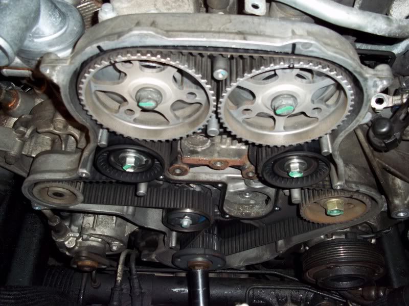
actually the IP pulley has 6 holes and is keyed. Atleast the one I'm sitting looking from an '06
what's missing the timing mark on the cover to key the pump too..I have been inside and replaced the CP3. I couldn't find any mark that made sense..yes I looked. just I looked for cam gear marks
I still don't the timing of the pump relative to the crank makes that much difference. it might make some but its a small amount.
from what I have read about the timing of the CP3 on the Cummins isn't a power issue but a noise issue. this make sense.
-dkenny
As mentioned, the cam gears do not need to be timed, the timing marks on the cam gears are not needed and there is no mark they need to line up with. However, the Injection pump is timed, though the timing may not matter other than for the service access. There is a mark, though it is hard to see being right below a bolt on the rear timing cover.
Here's a photo of the injection pump cam gear and timing mark. Photo is courtesy of Green Diesel Engineering (thanks Keith!):
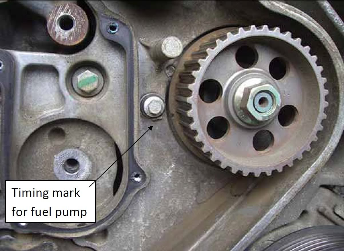
ANYWAY, anyone have a photo of the injection pump itself out of the vehicle??? I wanna see proof of it being keyed or not. lol
dkenny, if you are saying it is keyed (I think you were, though I think you were missing an "at" so it was a confusing statement), I believe you, if it is indeed keyed, and it has a timing mark to match on the housing behind the sprocket (which it does at least on my '05 I did my belt on), I think it best to put it in the correct position wether or not it is necessary. At least that's what I would do. It may or may not hurt performance or economy or be noisier, but you can't go wrong by putting it in its original engineered position.
P.S. I still want a photo of the keyed injection pump if someone has one? I'm curious what our specific pump looks like.
- Mark


 )...
)...
 ). I would assume the pump would have to be in a specific position and the sprocket lined up w/ something on the pump if disassembled/reassembled if the timing of the pump piston needed to be in line with an injection cycle - obvious.
  - however #2, the point is to get the most correct info on the board for reliable reference, so, if someone has pics, let 'er rip - as you may remember, I am one of the most voluble when someone posts misinformation, so it behooves me to correct and update my posts