Yeah, documentation would be VERY helpful. One thing that's always weird when working on older cars is that often times the documentation assumes certain tools or diagnostic procedures aren't available... I run into this a lot with older European cars where you need a magic factory tool, or resort to parts swapping. In 1985, that was the option. In 2020, you jump on Amazon and buy a $50 software oscilloscope and get the actual answer.

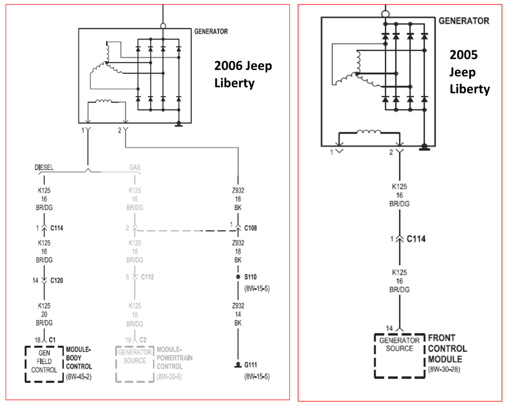
It could be that in 2005 the Jeep diagram wasn't deemed useful because nobody would have the tools for follow it.
Anyway, I think most of these computer controlled charging systems work in a similar manner - the control module correlates conditions (things like load, ambient temp, battery state of charge, etc.) and then uses pulse width modulation (PWM) to cause the regulator to switch the rotor’s field coils.... A higher duty cycle is more charging, and a lower duty cycle is less charging. GM does this with three wires IIRC (charging, sensing, control) but it could be done with two wires (charging+sensing, control). The difference would solely be where the control module gets current charge info... depending on how the car is wired, that variance could be big or small - but obviously in a car *designed* to have two wires, that would be accounted for. I think a lot of modern cars have a central or main battery distribution point for this purpose, so the control module can accurately measure alternator output and exert this control.
Here's an article on the topic specific to Chrysler:
https://autoprollc.com/wp-content/uploa ... ly_web.pdfOne thing that occurs to me, and probably worth keeping in mind, is that it seems the Liberty CRD doesn't behave like typical Mopars in most ways, so it wouldn't surprise me *at all* to find the Jeep's charging system is not Chrysler-like. But, there are some commonalities in the image WW posted and this article.
In that article, this bit:
Setpoint Regulation
To maintain the desired voltage setpoint, the regulator (PCM) controls either the power or ground circuit of
the rotor to maintain the proper magnetic field strength. The required current flow of the rotor varies based
on vehicle demand, battery state of charge and engine RPM. Chrysler applications have used both A and B
side regulation.
refers to the control module PWM control of the regulator.