Great write up...mucho thanks for taking time out to do it!!
I've already lost #1 glow plug, so like you, I decided to replace them all. Your write up convinced me to give it a shot myself. Now...to find the glowplugs....
Thanks again
| LOST JEEPS http://www.lostjeeps.com/forum/phpBB3/ |
|
| Glow Plugs R&R http://www.lostjeeps.com/forum/phpBB3/viewtopic.php?f=5&t=56696 |
Page 1 of 2 |
| Author: | BlackLibertyCRD [ Fri Nov 05, 2010 12:48 am ] |
| Post subject: | Glow Plugs R&R |
This is about how I went replacing the glow plugs. The service manual instruction are as follows: REMOVAL CAUTION: ² If necessary, remove hindering components to ease access. ² Do not bend, knock, or drop the glow plugs while handling (any mechanical impact may damage the glow plug). ² First loosen the glow plug with a wrench then screw it out by hand or with assistance of a flexible tool (e.g. with a rubber hose). ² Compare the removed glow plug with a new one. If there are missing parts of the ceramic heating element, remove all fragments from the combustion chamber before you start the engine. CYLINDER HEAD WILL NEED TO BE REMOVED 1.Disconnect negative battery cable. 2.To access the glow plug for cylinder number one, no additional components need to be removed. 3.To remove the glow plug for cylinder number two,remove the rear generator bracket. 4.To remove the glow plug for cylinder number three, remove the EGR pipe from the intake elbow and remove the intake elbow. 5.To remove the glow plug for cylinder number four, relocate the fuel filter assembly. 6.Disconnect glow plug electrical connectors. 7.Remove glow plugs from cylinder head. It sounds easy but if you just go at them just one at a time, it will be more difficult than needed. What I did was get all obstruction out of the way before removing any glow plugs. First disconnect battery cable. Afterward I laid a fender cover over the battery and left fender. I then put my magnetic tray on the radiator cross-member to keep bolts from getting lost. Remove oil cap, remove engine cover and put oil cap back on. Next is to remove obstruction so yo can get to the glow plugs and wiring. The alternator bracket is just behind the alternator and is triangle shape and connect to the intake Remove the rear alternator bracket using a 15 mm socket and extension near the rear of the alternator and 13 mm wrench on the two bolts on the intake. There is the glow plug harness there, Unplug it and move both ends out of the way. Next step is to move the fuel filter assembly out of the way. I remove the two nuts ( 13 mm wrench) holding it, disconnected the lines and wiring. I put the filter assembly upright on the bench and move the hoses and wiring out of the way. Now to tackle the intake elbow takes a little more work but is easier to get to with the first two items out of the way. You will need a gasket. Remove the vacuum hose from the pipe at the intake elbow for the brake booster and the bolt (8 mm) that hold the vacuum pipe. Loosen the EGR pipe clamp (underneath elbow 7 mm socket ¼ drive deep) from the elbow and 2 flange bolts (10 mm socket 3/8 drive) EGR pipe to cooler. Best to get those two bolts from under Jeep just above the starter. Then the pipe should swing loose and still be connected to the intake elbow. Remove the hose from the FCV and disconnect the wire and move both out of the way as much as you can. Remove the 4 intake elbow bolts as following: Right rear, use a 8 mm box Right front use a 8 mm ¼ drive socket and extension working with hand from under the elbow and using the socket to guide the bolt down and under the elbow. Left front with dipstick tube and left rear bolt comes out easy with a 8 mm ¼ drive socket. Do these bolts last when taking off the elbow and first when putting is back together. That way there is less fuss with the two inner or right side bolts. The elbow should be loose except for a EGR cooler bracket that holds a EGR cooler line. The elbow will now be able to move down and out enough to get number 3 glow plug. Now it time to use long pliers or fingers to disconnect the wiring from the glow plugs by pulling straight out. Remove the glow plugs with a 10 mm socket 3/8 drive deep with an extension. They all came out easy and the threads were fairly clean as they should be. If fact they felt a little loose but was not leaking as far as I can see. Be sure not to over torque the new ones. INSTALLATION CAUTION: ² Before a new glow plug is installed, make sure that the thread of glow plug and glow plug bore in the cylinder head is dry, clean, and oil/grease-free ² Check the resistance of the glow plug with an appropriate multi-meter, resistance should be less than 0.8V. ² Tighten the glow plug by hand or means of a flexible tool (e.g. rubber hose) as far as possible and finish tightening with a correctly set torque wrench. ² Strictly observe the required tightening torque. ² Do not bend, knock, or drop the glow plug while installing. CAUTION: If a fragment of the ceramic heater of the glow plug has fallen into the combustion chamber, the cylinder head MUST be removed. 1. Install glow plugs all the way into cylinder head, hand tight, until the thread stops. CAUTION: Strictly observe the required tightening torque. If tightening torque was to high, remove and replace the glow plug. 2. Tighten glow plugs to 12.5 N·m (110 in. lbs.). 3. Connect glow plug electrical connectors. 4. Install any components that were removed for access. I use a long vacuum hose to install each glow plugs by hand so there wasn't any possibility of dropping a glow plug at over $30 apiece. Reverse the process to install all items removed to get to the glow plugs. Be sure to bleed the filter assembly before trying to start engine. I hope this is easy enough for all to follow. |
|
| Author: | racertracer [ Fri Nov 05, 2010 2:10 am ] |
| Post subject: | Re: Glow Plugs R&R |
Excellent, and all this for just a pat on the back... imagine that. Superbly done. This glow plug replacement procedure will be printed and kept in my CRD repair notes. Thank you. |
|
| Author: | Silverdiesel [ Sat Nov 06, 2010 3:12 pm ] |
| Post subject: | Re: Glow Plugs R&R |
I'm going after GP #4 - removing the fuel manager head will be no problem as thats how I replace fuel filter anyway...... Good write up - Ads/Mods>> get this to CRD Tech if it is not there already... Roland |
|
| Author: | SmokinJoe [ Sat Nov 06, 2010 3:37 pm ] |
| Post subject: | Re: Glow Plugs R&R |
Great write up...mucho thanks for taking time out to do it!! I've already lost #1 glow plug, so like you, I decided to replace them all. Your write up convinced me to give it a shot myself. Now...to find the glowplugs.... Thanks again |
|
| Author: | BlackLibertyCRD [ Sat Nov 06, 2010 8:01 pm ] |
| Post subject: | Re: Glow Plugs R&R |
Bosch # 80041 http://www.summitracing.com/parts/BCH-80041 http://www.oxygensensor.net/bosch_sp/80041.php check shipping for total cost |
|
| Author: | BlackLibertyCRD [ Sat Nov 06, 2010 8:04 pm ] |
| Post subject: | Re: Glow Plugs R&R |
Silverdiesel wrote: I'm going after GP #4 - removing the fuel manager head will be no problem as thats how I replace fuel filter anyway...... Good write up - Ads/Mods>> get this to CRD Tech if it is not there already... Roland Yes, you are right, This should be in tech section. How do I move it there?? |
|
| Author: | Silverdiesel [ Sun Nov 07, 2010 11:29 pm ] |
| Post subject: | Re: Glow Plugs R&R |
If this is to become CRD Tech then here is more detail on #4 Glow Plug replacement. Test probe revealed 148 ohms (resistance high P1267 CEL on)Red arrow is #4 plug wire, yellow is void where fuel manager/filter was removed... 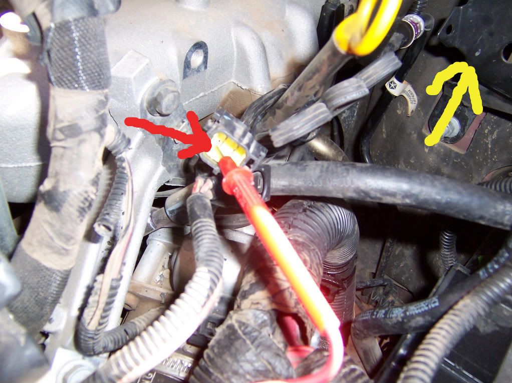 black hole were plug is again arrow (way in there!), 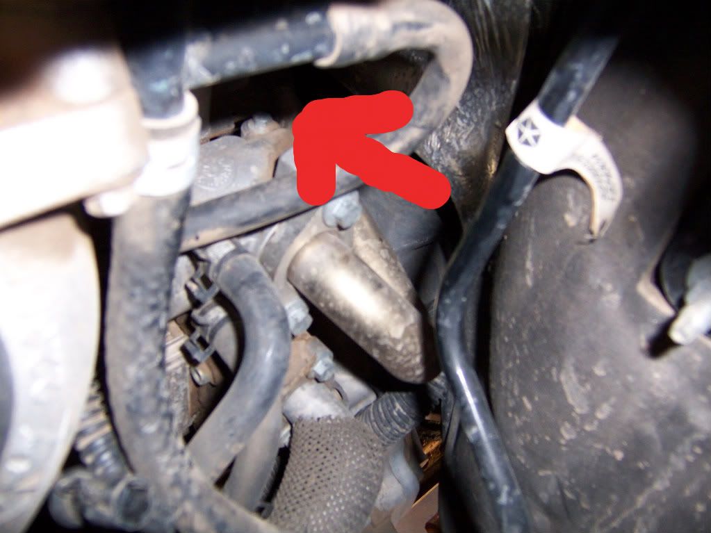 bad and new, 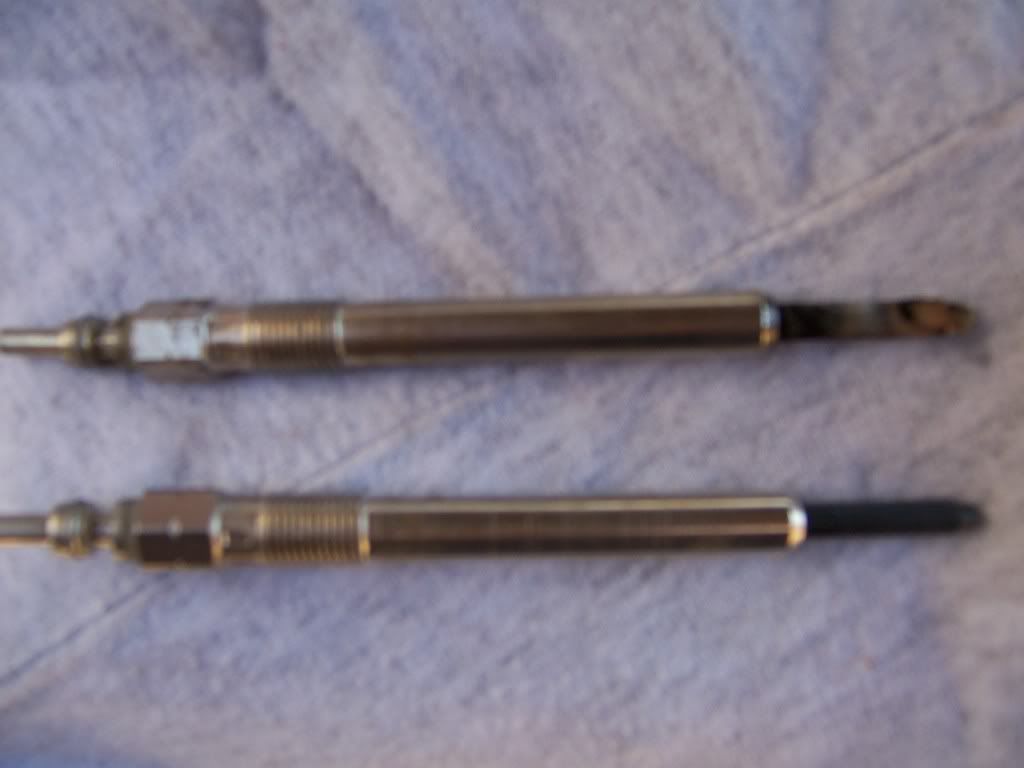 new installed, 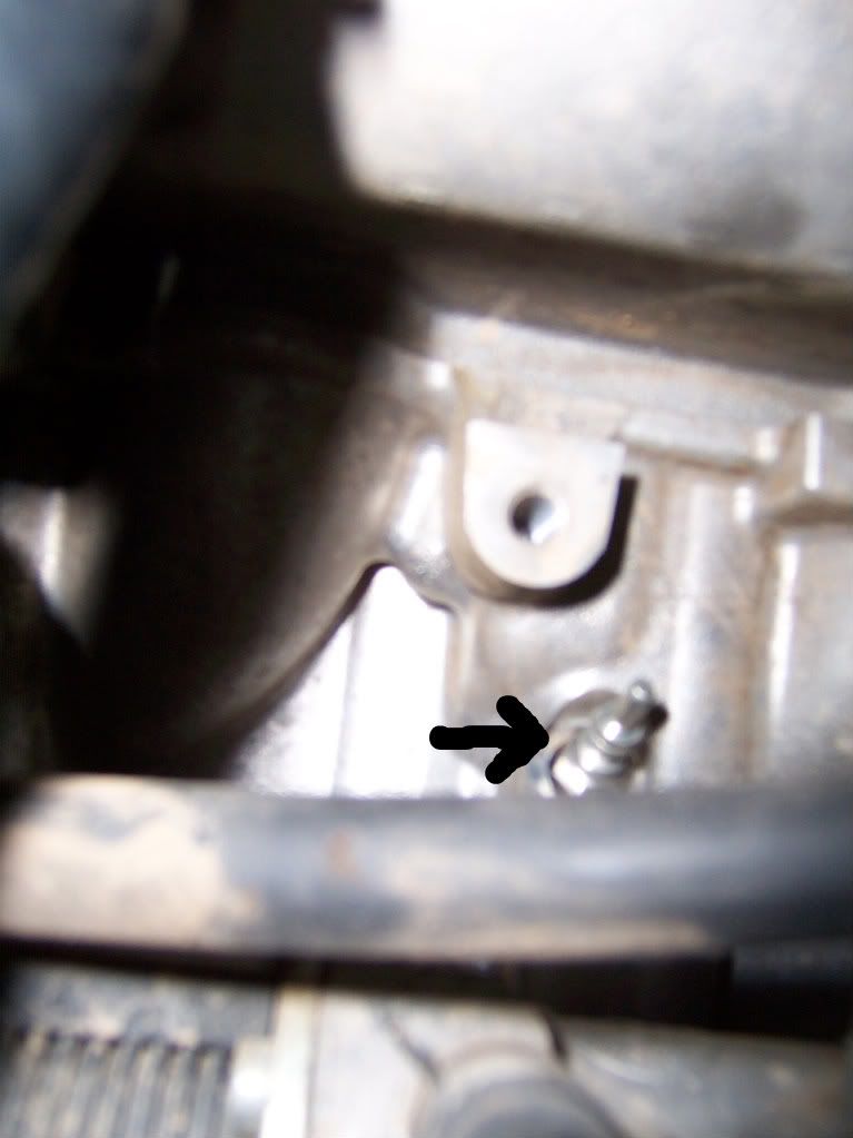 wire recapped on new plug, 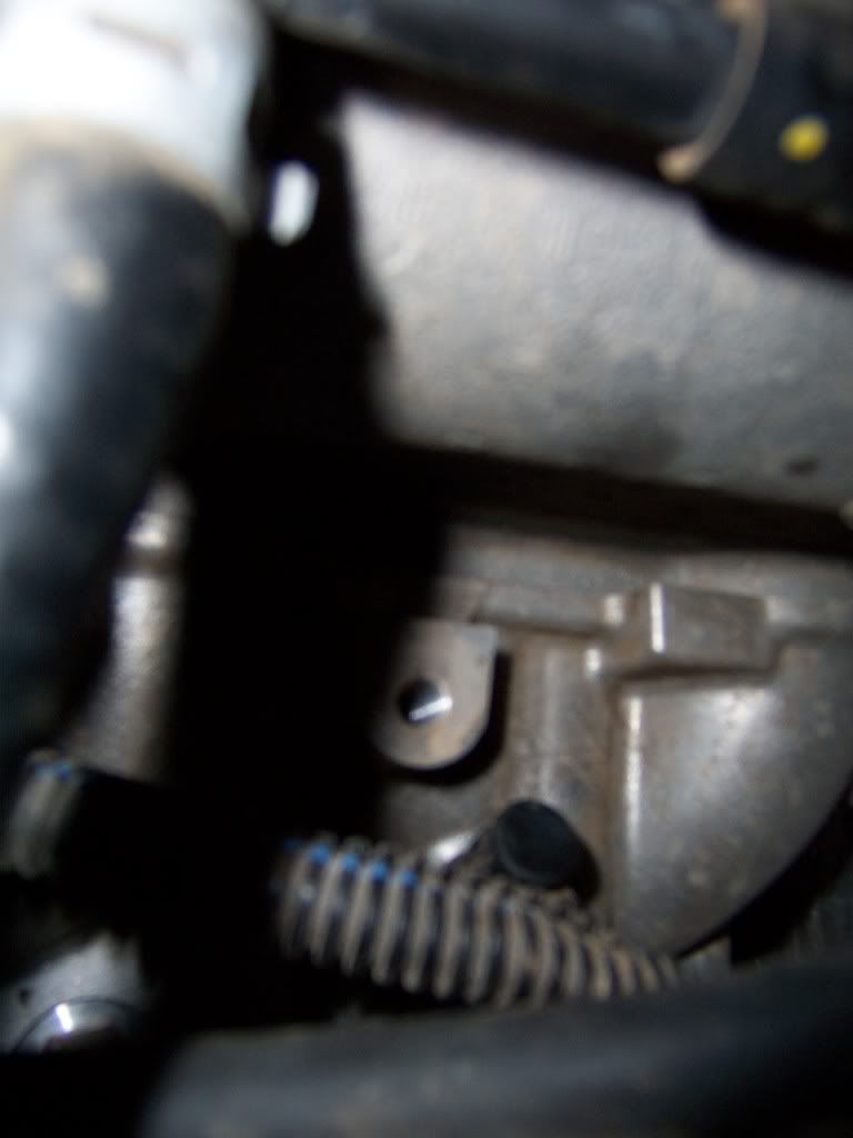 final test range should be .7 to 1.1 ohm IIRC, 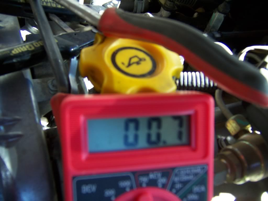 returned fuel manager with proper priming procedure and such and cleared code and all worked!! HTH Roland |
|
| Author: | ATXKJ [ Mon Nov 08, 2010 9:23 pm ] |
| Post subject: | Re: Glow Plugs R&R |
I would add the caution that some glow plugs have broken when taken out. |
|
| Author: | nivram [ Fri Dec 10, 2010 6:39 pm ] |
| Post subject: | Re: Glow Plugs R&R |
ATXKJ wrote: I would add the caution that some glow plugs have broken when taken out. Could you elaborate on this? This has happened to my sons 06, is there some way to remove the broken piece? what might be recommended? Marv. |
|
| Author: | VMKJCRD [ Fri Dec 10, 2010 7:23 pm ] |
| Post subject: | Re: Glow Plugs R&R |
BlackLibertyCRD wrote: CAUTION: If a fragment of the ceramic heater of the glow plug has fallen into the combustion chamber, the cylinder head MUST be removed. |
|
| Author: | ATXKJ [ Fri Dec 10, 2010 8:00 pm ] |
| Post subject: | Re: Glow Plugs R&R |
nivram wrote: Could you elaborate on this? This has happened to my sons 06, is there some way to remove the broken piece? what might be recommended? Marv. I didn't break it - the dealership did (Star told them to change all 4 because I had a continuing problem with #2) - and they pulled the head & sent it to a machine shop to put the GP out. |
|
| Author: | warp2diesel [ Fri Dec 10, 2010 10:38 pm ] |
| Post subject: | Re: Glow Plugs R&R |
BlackLibertyCRD wrote: Bosch # 80041 http://www.summitracing.com/parts/BCH-80041 http://www.oxygensensor.net/bosch_sp/80041.php check shipping for total cost FYI: Summit is on back order until at least the 20th. |
|
| Author: | MrMopar64 [ Sat Dec 11, 2010 10:16 am ] |
| Post subject: | Re: Glow Plugs R&R |
Bosch stopped making the ceramic glow plug, so they'll never get any more... The metallic is where it's at... |
|
| Author: | nivram [ Sat Dec 11, 2010 11:22 am ] |
| Post subject: | Re: Glow Plugs R&R |
Well thanks for those replies. He ended up trucking it off to a repair shop to have it done. When I told him of stuff that I had read here, he said that he got the seven volt GP because of the vin number, and he said it seamed to have a lot of cermic in it. So we'll see what happens when he gets it back. Thanks again for the help. #3 he has had to do twice before, now this is the third time. To bad some one hasen't come up with a better way to heat the cold start like a grid heater. Marv. |
|
| Author: | BlackLibertyCRD [ Sat Dec 11, 2010 11:27 pm ] |
| Post subject: | Re: Glow Plugs R&R |
MrMopar64 wrote: Bosch stopped making the ceramic glow plug, so they'll never get any more... The metallic is where it's at... MrMopar64, can you give us the total scoop of whats happening with the glow plugs. New Kit, controller, flash maybe???? |
|
| Author: | painemann [ Tue Dec 14, 2010 10:40 pm ] |
| Post subject: | Re: Glow Plugs R&R |
Silverdiesel wrote: If this is to become CRD Tech then here is more detail on #4 Glow Plug replacement. Test probe revealed 148 ohms (resistance high P1267 CEL on)Red arrow is #4 plug wire, yellow is void where fuel manager/filter was removed... black hole were plug is again arrow (way in there!), bad and new, new installed, wire recapped on new plug, final test range should be .7 to 1.1 ohm IIRC, returned fuel manager with proper priming procedure and such and cleared code and all worked!! HTH Roland Is there a write up on how to test them? (final test range should be .7 to 1.1 ohm) Got that but which pins in the connector are you using? Oh and thanks for the replacement write up, well done! Hope I don't need it until the metallic ones are easy to come by! |
|
| Author: | Drewd [ Wed Dec 15, 2010 1:51 am ] |
| Post subject: | Re: Glow Plugs R&R |
In my opinion based on my experiences of getting MIL lights for glow plugs, anything above .7 ohms was a failed plug with an undervoltage MIL code and harder starts. |
|
| Author: | dieseldoesit [ Wed Mar 07, 2012 11:05 am ] |
| Post subject: | Re: Glow Plugs R&R |
One thing that might want to be added is that there is a mount for the heater line on the engine side of the FCV. Removing this bolt (7 or 8 MM) allows you to move the intake completely out of the way. Excellent writeup. Thank you very much, it helped tremendously!! |
|
| Author: | SLS [ Fri Aug 03, 2012 10:30 am ] |
| Post subject: | Re: Glow Plugs R&R |
BlackLibertyCRD wrote: This is about how I went replacing the glow plugs. The service manual instruction are as follows: REMOVAL CAUTION: ² If necessary, remove hindering components to ease access. ² Do not bend, knock, or drop the glow plugs while handling (any mechanical impact may damage the glow plug). ² First loosen the glow plug with a wrench then screw it out by hand or with assistance of a flexible tool (e.g. with a rubber hose). ² Compare the removed glow plug with a new one. If there are missing parts of the ceramic heating element, remove all fragments from the combustion chamber before you start the engine. CYLINDER HEAD WILL NEED TO BE REMOVED 1.Disconnect negative battery cable. 2.To access the glow plug for cylinder number one, no additional components need to be removed. 3.To remove the glow plug for cylinder number two,remove the rear generator bracket. 4.To remove the glow plug for cylinder number three, remove the EGR pipe from the intake elbow and remove the intake elbow. 5.To remove the glow plug for cylinder number four, relocate the fuel filter assembly. 6.Disconnect glow plug electrical connectors. 7.Remove glow plugs from cylinder head. It sounds easy but if you just go at them just one at a time, it will be more difficult than needed. What I did was get all obstruction out of the way before removing any glow plugs. First disconnect battery cable. Afterward I laid a fender cover over the battery and left fender. I then put my magnetic tray on the radiator cross-member to keep bolts from getting lost. Remove oil cap, remove engine cover and put oil cap back on. Next is to remove obstruction so yo can get to the glow plugs and wiring. The alternator bracket is just behind the alternator and is triangle shape and connect to the intake Remove the rear alternator bracket using a 15 mm socket and extension near the rear of the alternator and 13 mm wrench on the two bolts on the intake. There is the glow plug harness there, Unplug it and move both ends out of the way. Next step is to move the fuel filter assembly out of the way. I remove the two nuts ( 13 mm wrench) holding it, disconnected the lines and wiring. I put the filter assembly upright on the bench and move the hoses and wiring out of the way. Now to tackle the intake elbow takes a little more work but is easier to get to with the first two items out of the way. You will need a gasket. Remove the vacuum hose from the pipe at the intake elbow for the brake booster and the bolt (8 mm) that hold the vacuum pipe. Loosen the EGR pipe clamp (underneath elbow 7 mm socket ¼ drive deep) from the elbow and 2 flange bolts (10 mm socket 3/8 drive) EGR pipe to cooler. Best to get those two bolts from under Jeep just above the starter. Then the pipe should swing loose and still be connected to the intake elbow. Remove the hose from the FCV and disconnect the wire and move both out of the way as much as you can. Remove the 4 intake elbow bolts as following: Right rear, use a 8 mm box Right front use a 8 mm ¼ drive socket and extension working with hand from under the elbow and using the socket to guide the bolt down and under the elbow. Left front with dipstick tube and left rear bolt comes out easy with a 8 mm ¼ drive socket. Do these bolts last when taking off the elbow and first when putting is back together. That way there is less fuss with the two inner or right side bolts. The elbow should be loose except for a EGR cooler bracket that holds a EGR cooler line. The elbow will now be able to move down and out enough to get number 3 glow plug. Now it time to use long pliers or fingers to disconnect the wiring from the glow plugs by pulling straight out. Remove the glow plugs with a 10 mm socket 3/8 drive deep with an extension. They all came out easy and the threads were fairly clean as they should be. If fact they felt a little loose but was not leaking as far as I can see. Be sure not to over torque the new ones. INSTALLATION CAUTION: ² Before a new glow plug is installed, make sure that the thread of glow plug and glow plug bore in the cylinder head is dry, clean, and oil/grease-free ² Check the resistance of the glow plug with an appropriate multi-meter, resistance should be less than 0.8V. ² Tighten the glow plug by hand or means of a flexible tool (e.g. rubber hose) as far as possible and finish tightening with a correctly set torque wrench. ² Strictly observe the required tightening torque. ² Do not bend, knock, or drop the glow plug while installing. CAUTION: If a fragment of the ceramic heater of the glow plug has fallen into the combustion chamber, the cylinder head MUST be removed. 1. Install glow plugs all the way into cylinder head, hand tight, until the thread stops. CAUTION: Strictly observe the required tightening torque. If tightening torque was to high, remove and replace the glow plug. 2. Tighten glow plugs to 12.5 N·m (110 in. lbs.). 3. Connect glow plug electrical connectors. 4. Install any components that were removed for access. I use a long vacuum hose to install each glow plugs by hand so there wasn't any possibility of dropping a glow plug at over $30 apiece. Reverse the process to install all items removed to get to the glow plugs. Be sure to bleed the filter assembly before trying to start engine. I hope this is easy enough for all to follow. Thought I would bring this back to the front. (less search time) This was real helpful when I unexpectedly had to replace a GP to pass a newly revised NY inspection law. Thanks to one of my CRD owner friends in Florida, who had already replaced his GPs and sent me his old ones. I was able to replace the faulty #2 GP & pass inspection. They are right about getting everything out of the way before you start to actually tackle the GP removal. I even took the battery out. It gave me a shelf to lay tools on & I could almost see the #2 GP. Next: Replace the GP with the Etecno 7 volt metallic glow plugs (GX3123). I saw a report by GDE that the new plug is the same length as the stock ceramic, so protrusion into the cylinder head is correct. The Etecno plug also has similar resistance to a Bosch Ceramic, so no check engine light and the diagnostic function works correctly. |
|
| Author: | Hexus [ Sat Aug 04, 2012 8:45 am ] |
| Post subject: | Re: Glow Plugs R&R |
Yes, the Etecnu's do not throw a CEL, I have them in mine and it was nice to not have to flash the ECU for 5v instead of 7v. My Chrysler dealer did say there were still 7v kits out there with all 4 glow plugs for around $210, and that was only in June 2012, so the 7v's are still out there. I would definitely recommend getting the Etecnu's just because they're metal and you don't have to worry about the ceramic breaking in them. |
|
| Page 1 of 2 | All times are UTC - 5 hours [ DST ] |
| Powered by phpBB © 2000, 2002, 2005, 2007 phpBB Group http://www.phpbb.com/ |
|