Best I can do by hand with analog calipers.
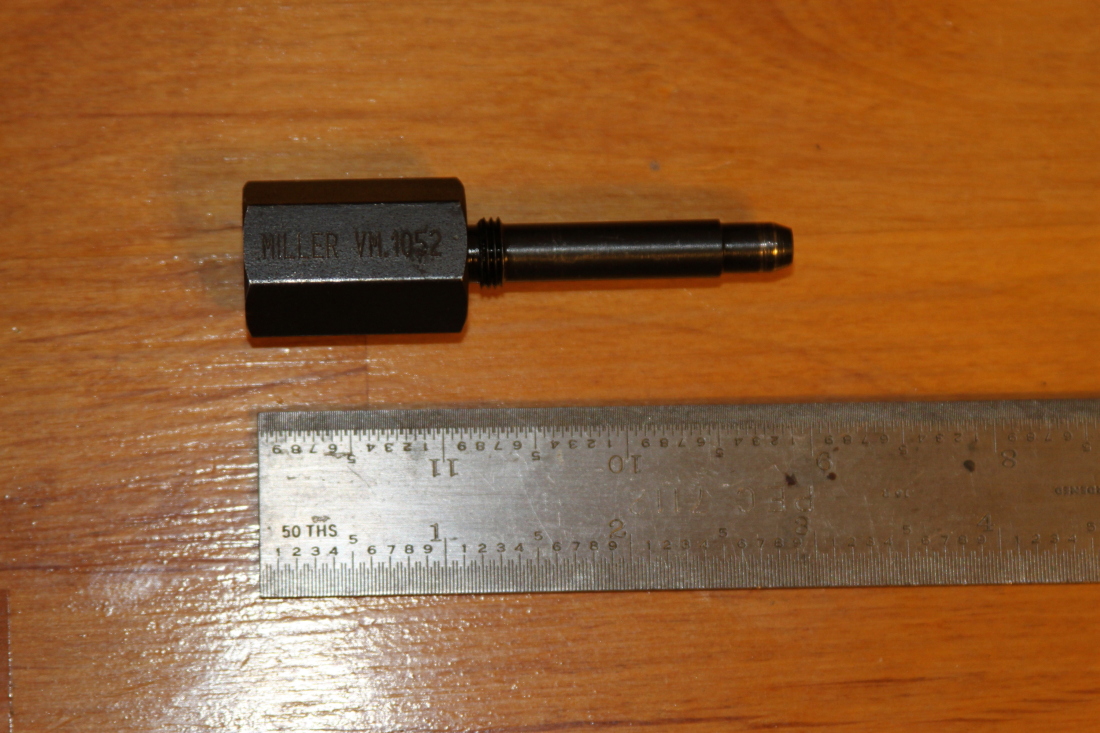
Miller 1052 - Intake pin

Hex head - 0.75" across flats
Overall length 2.96"
Shaft length (base of hexagonal head to tip including threaded section) - 1.76"
Shaft diameter of the thicker section - 0.315" for 1.39" of the above shaft length (Note diameter of threaded section is 0.391")
Shaft diameter of 1st step down of the tip section - 0.275" for 0.3" of the above shaft length
the final 0.08" of the above shaft length is beveled at something like a 75 degree angle to create a 0.2" diameter flat at the pin's tip - I presume this bevel is to help guide the pin into the cam pin hole and that the 0.275" section is what actually locks the cam in place hence that is the critical dimension.
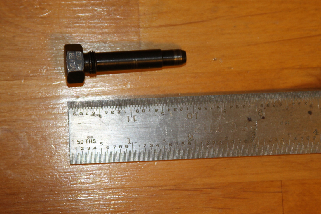
Miller 1053 - Exhaust pin - identical except as noted below

Hex head - 0.58" across flats
Overall length 1.932"
Shaft length (base of hexagonal head to tip including threaded section) - 1.65"
Shaft diameter of the thicker section is the same but the length of that section is only 1.25" of the above shaft length.


