A dissertation on the KJ fuel manager, a filter head with electric heater and inlet fuel temperature sensor
View of removable heater puck is from the filter side, orienting the Fuel Heater to the driver-side of the vehicle
The heatable head accepts a screw-on fuel filter with integral water-in-fuel sensor and drain. The area above the filter contains a 12v electric
heater which is normally submerged in fuel - the heater is comprised of seven (7) positive-coefficient resistive disk elements held in place between two
aluminum plates which transfer heat into the surrounding fuel - the heater recieves power from the IGN switch at key-on, and the resistive
heater elements activate at ~40*F, warming the resident fuel in the filter - rising temperature increases element resistance, slowly turning them off as fuel temperature rises to acceptable operating values
Catastrophic failure in the heating element occurs when air has leaked into the fuel line back at the tank and is drawn into the fuel head with
the fuel - fuel, denser than air, settles to the bottom of the filter - air, being lighter than fuel, accumulates in the area above the
filter where the heater is located - the heater requires fuel density to control rate of heat rise - repeated rapid rise in air alone eventually
burns the hermetic seal in the connector, damaging the harness plug, with resultant fuel leak-thru
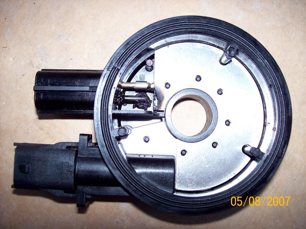
This illustrates catastrophic failure of the heating element connector - upper terminal conducts heater current to the aluminum plate beneath the disks - lower terminal connection to upper plate has
been burned-thru - the seven dots in the circle are electrical terminals for the heater-discs - unseen beneath the plate are the opposite
electrical terminals on the lower plate - the lower terminal would conduct heater current thru the aluminum plate to the upper disk terminals, butcept it's burned open
- luckily, in this case, without any resultant fire
The Fuel Temperature Sensor is located in the bottom connector - as can be seen, it is isolated from the fuel above the filter cannister, and does not
function to measure fuel heated by the Fuel Heater element - it resides in the chamber above which connects directly to the port for incoming
fuel from the fuel tank - thus it senses temperature of pre-filtered fuel which has not passed into the fuel filter and been further heated by engine bay heat
The ECM uses the FTS to determine whether incoming fuel is too hot to be useable - the cooler fuel flowing from the tank is used to cool the CP3,
keeping it within spec'ed limits to prevent galling the 30,000psi hi-pressure plungers, causing the CP3 to sieze-up
ECM senses high temp fuel from the tank, commands the Fuel Quantity Solenoid on the CP3 to limit fuel to the hi-pressure gallery, being input from the low-pressure gallery - the
Cascade Overflow Valve in the low-pressure gallery then bypasses all excess fuel, which is much cooler than that fuel returned from the rail and injectors, back to the
fuel tank - constant volume of air-flow beneath the vehicle and across the fuel tank then brings tanked fuel down to acceptible operational
temperatures - ECM commands FQS to allow more volume for the rail, rail excess dumps back to the tank, and it's deja vu all over again*
The fuel heater can be disabled with little detrimental effect - the Fuel Temperature Sensor must be connected at all times to prevent
catastrophic damage to the CP3 - fuel thermal expansion of 'only a couple percent' can severely damage an injection pump with
only a couple
micro-percent allowable variation in spec'ed plunger\barrel clearances
*Likely, this is prime reason why GM Duramax Diesel vehicles are factory-equipped with return-fuel cooler systems - BOSCH officially notes that
some CP3 fuel supply systems should be equipped with a return-fuel cooler system
I presumed this could be specifically aimed at the short-wheelbase KJ with short return-fuel line preventing sufficient thermal conduction into ambient air-over flow


