ITS FINE TO FOLLOW "REMOVAL" PROCEDURE, BUT DO NOT UNSCREW THE 29MM (1 1/8TH) CAP-NUT off the top-portion of the injector itself.
Don't make my mistake; do not disassemble an injector. Unless you have the proper knowledge, experience, psrts and tools you will only damage and/or miscalibrate the injector.
#4 INJECTOR REMOVAL TIPS:
A#1: IF YOU HAVE AIR, BLOW THE CRAP OUT OF THE INJECTOR AREA BEFORE, repeat BEFORE , YOU DISCONNECT ANY FUEL LINES OR REMOVE THE INJECTOR!!!* Then use rags to clean the area as much as you possibly can BEFORE PULLING THE INJECTOR! You want to eliminate the danger of any crap whatsoever falling into the cylinder when you remove the injector! This advice applies equally to those using the magnificent Miller injector removal tool as well as we neanderthals.
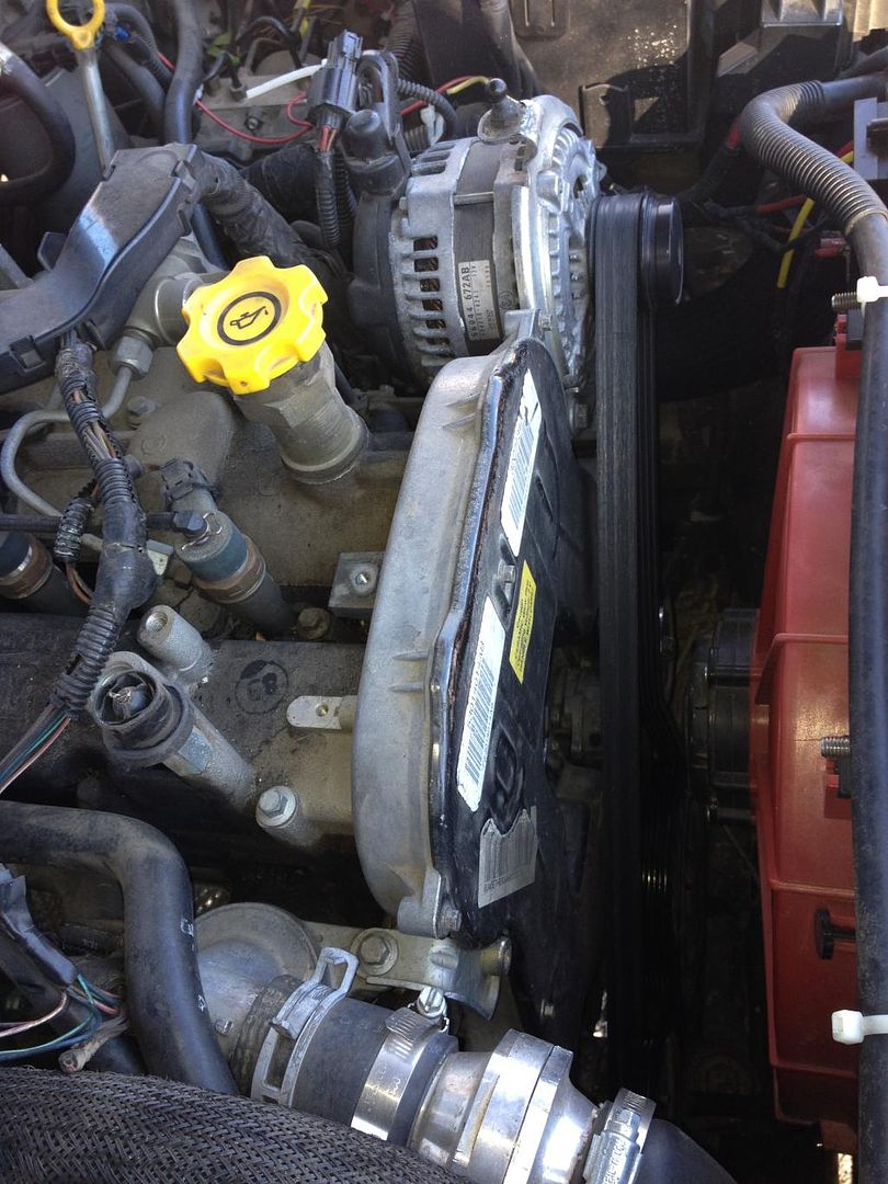
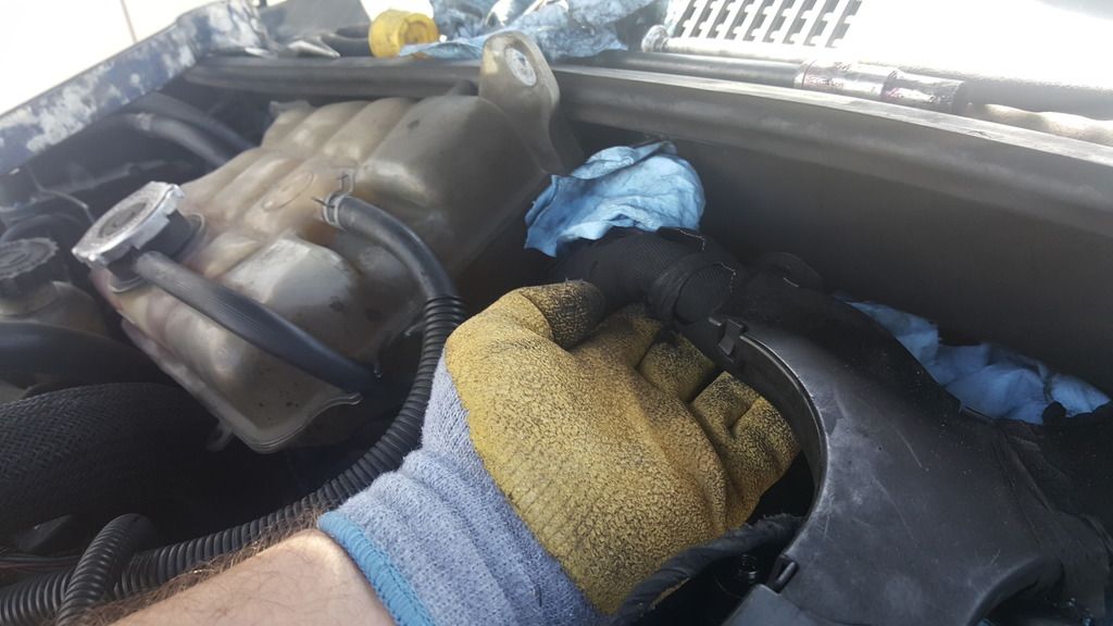
B.The over-engine wiring "spider" is a pita obstacle. It runs over-engine then along the firewall behind the coolant reservoir. To create some play to permit shifting the spider a bit (as necessary to fit hands/tools around the #4/back/rear injector), first remove the 10mm nut that secures the wiring spider's black plastic cover to the back-left (facing engine) of the valve cover (while there, remove the vertical stud it's attached to; more room for wrench-rotation). Next, remove the coolant reservoir's two 10mm mounting nuts, then carefully pull the reservoir forward enough to allow some play in the spider.
C. Remove Injector electrical connectors from BOTH #3&4 (#3 to provide more working room).
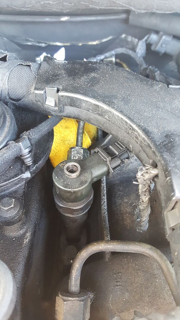
D. Only disconnect #4 fuel line at injector, but completely remove #3 fuel line entirely. Again, more working room, and also reduces the likelihood of damaging the #3 line while wrestling the #4 injector.
#3 line contrasted in front of yellow rag; its removal provides greatly improved visual and manual access to #4:
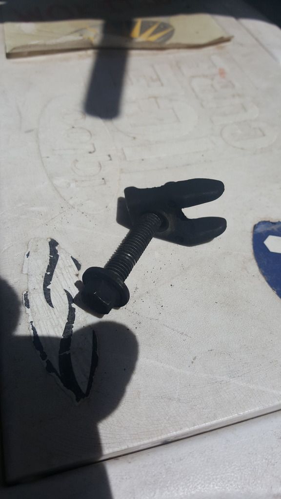
E Obviously, don't forget to remove #4 injector's base "retainer crow" bolt and crowfoot-fitting.
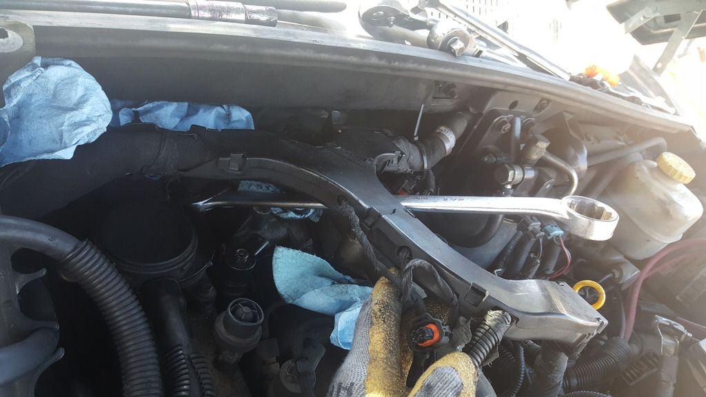
F. In spite of the painful lesson from (stupidly) COMPLETELY removing the injector cap (DON'T!), to help loosen and remove a stubborn injector, IF NECESSARY I still advocate taking advantage of the cap nut's 29mm hex to GENTLY 1/8th-rotate the top section of the injector back-n-forth (neither loosening nor tightening the cap!) enough to help loosen its base. Pull directly up on the injector while simultaneously rotating back and forth. Thanks to PB-soaking overnite, it actually wasn't that bad (for #4).
Best wrench angle:
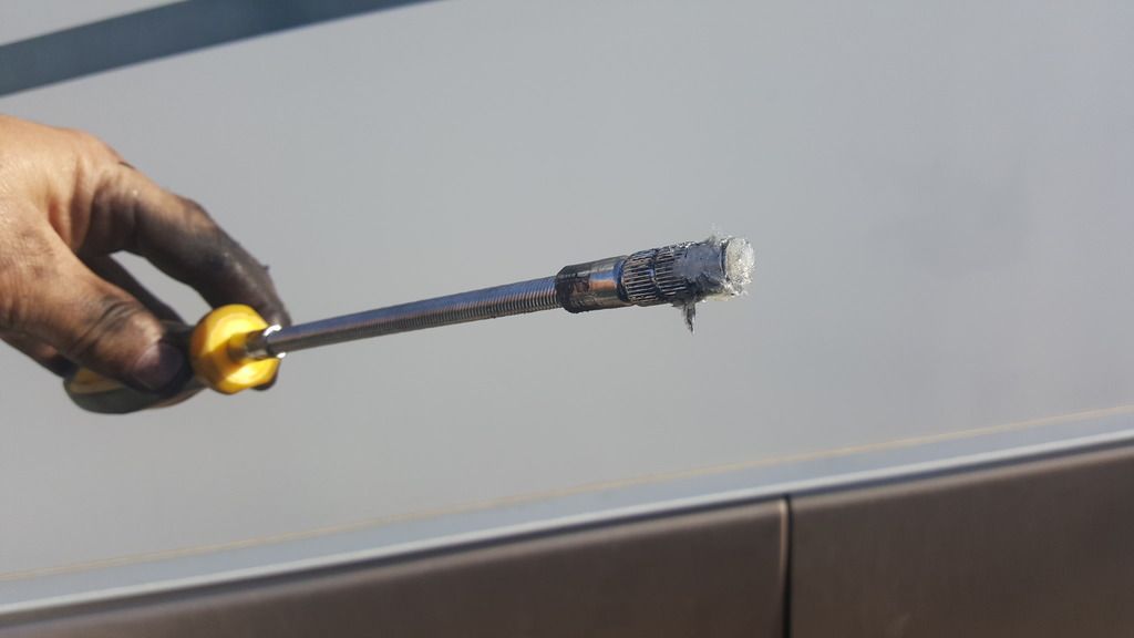
*Lacking air tools in the field, my 'cleaning' solution was to use vaseline on the end of a flex-shaft screwdriver with no tip inserted. After the injector was removed, the same method also worked great for cleaning the injector shaft and base (flex-shaft driver is too big to fall into the cylinder!). It probably took 50 "coat, dip, clean; coat, dip, clean"s before the injector base and shaft were clean, but it seems to have worked very well. In fact, the flex-driver/vaseline combo extracted the old crush-washer on the 30th 'dip'. Yeah!
Cell-pics of #4 injector-base before/after cleaning with flex-vas:


Hardly perfect, but clean enough that the fresh crush-washer has been airtight post-op.
The incredible amount of crap around #4's base was my fault. While on a week-long road trip my #4 fuel line started leaking. Not too bad, and I didn't have tools with me, so I let it flow for maybe four days of driving. DON'T DO THAT! I am now certain that the diesel pooling and seeping into the #4 injector base is what caused both my air leak AND the accumulation of crap around the injector. Stupid. All it would have required was a 17mm wrench and 5 minutes to snug the line and stop the fuel leak. Argh.
Suerte.
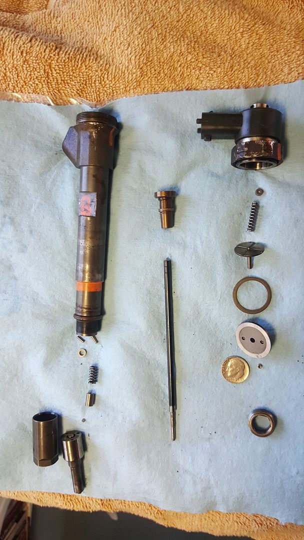
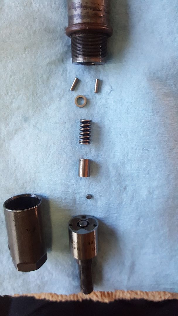
HERE'S EXPLODED PICS OF FULLY DISASSEMBLED INJECTOR. I haven't received my "Lebowski Injector-Tech Junior Achiever" plaque, but there's always next year, (sigh). Will post tech notes to accompany pics soon..
The injector pics should satisfy mechanical curiosity and maybe give someone in a jam a fighting chance for a field fix (improbable)
All parts to the right of the main injector body fit between the cap and body in the top portion of the injector (the dime is pictured for scale).
The parts on the lower left beneath the main body are the lower components.
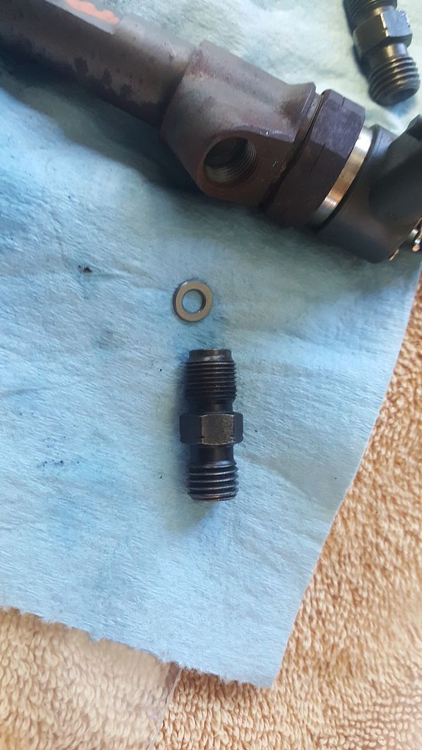
There's a washer between the injector and its fuel line fitting.
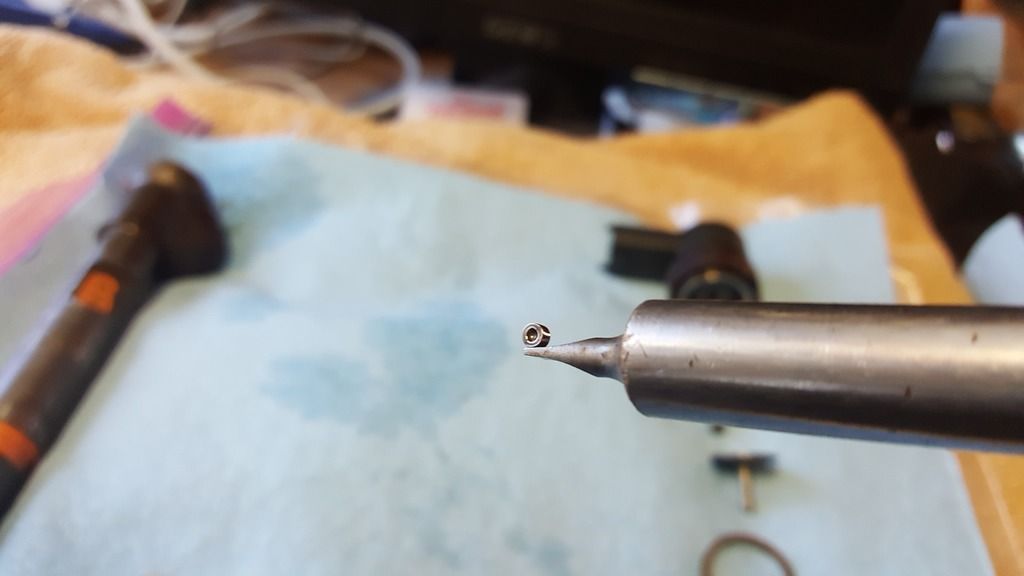
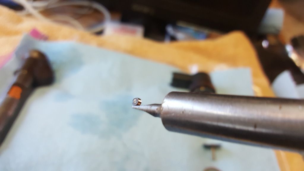
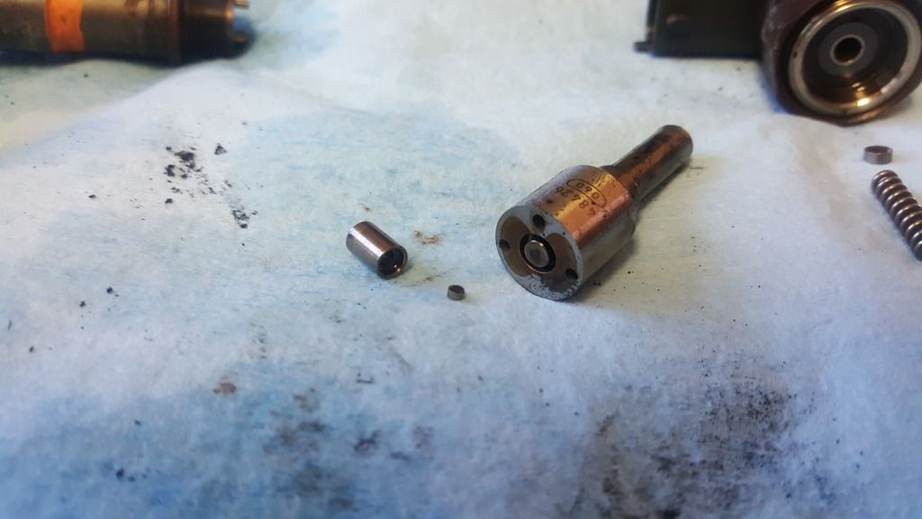
Below are pics of the small jet from the upper-injector exploded view above, perched on the blade of a magnetic screwdriver (zoom in). Note the dome-shaped recess in first pic below; it faces downward within the center tube of the lower plunger and cups a miniscule ball-bearing (absent). The second pic shows the jet's flat flipside.
Lower portion assembled.
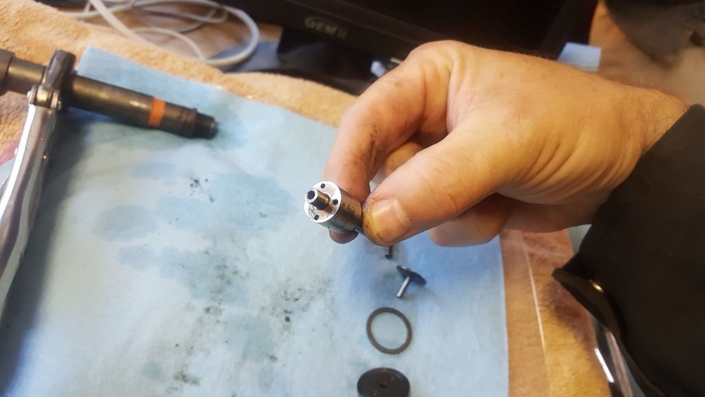
Lower portion disassembled; note the small jet.
I'll enhance the above coloring-book with actual injector-tech info as acquired.
Or maybe someone else cares to pipe-in some techno-smarts...?