LOST JEEPS http://www.lostjeeps.com/forum/phpBB3/ |
|
Notes from Cylinder Head R&R http://www.lostjeeps.com/forum/phpBB3/viewtopic.php?f=5&t=85466 |
Page 1 of 4 |
Author: | Gypsy62 [ Thu Oct 20, 2016 5:40 pm ] |
Post subject: | Notes from Cylinder Head R&R |
< Given that I've been polluting this forum for months with separate threads pleading for salvation throughout this major surgery, I'm going to condense and consolidate all of that fantastic advice and insight into this thread and credit the advising Supertechs. A dignified and chivalrous platoon of scholars and humanitarians, All. Many MANY thanks to: BUGNOUT, CEVANS, DENT, DHENDERZ, DREWD, FLASH, FLMAN, GEORDI, GORDNADO, HEXUS, JSAMPS1345, JWS84_02, LACABRERA, LANCER, LOCKED KJ, MASS-HOLE, MOUNTAINMAN, OLYPOPPER, PAPAINDIGO, PETEYZ24, PJIGAR, RANKOM, SIR SAM, THEFUNK, THERMOREX, TJKJ2002, WOODTICK, WWDIESEL, 95Z28A4. Apologies to any others I may have overlooked whom have kindly indulged my newbie threads. YOU GUYS ARE ALL HEROES !!! > HEAD/ARP/TBELT-INSTALL REVIEW (imho) A1: evaluate what work needs to be done to your cylinder-head. In my case, this HG job was just preventative; no leaks, warps, dropped-valves, glo-tips or other disasters. Still, I opted to install new exhaust-valves & valve seals (both exh/int). I had a machine-shop: A. Tank-clean both the head and intake man/cam assembly. B. Grind the valve seats. C. Surface the cylinder head. I also had them install the new exhaust-valves and int/exh stem seals. Use good judgment; the money you spend addressing head/valve issues while the head is off can repay you 10x against future failure. While your head is being serviced, use fresh motor oil to slick a coat of protection on the exposed surface of the block and pistons; then cover with lint-free rags until head installation. Before head installation, use metal-cleaner (brake-cleaner spray adequate) to remove oil residue, and make absolutely certain that the mating surfaces are clean and dry. While the HEAD is off it's an excellent time to: - Replace the motor mounts; tons of access and you're only wrestling the weight of the jacked-up short-block (=300# lighter than complete engine&accessories). - Replace glo-plugs, sparing some installation grief (post-machining). While the INTAKE/CAM assembly is off: - Remove and clean your MAP and CCV using sensor-safe spray cleaner. With all sensors and seals removed, it's also advisable to have a machine-shop tank-clean the entire assembly (or at least DIY spray-clean). The cams/bearings will not be adversely affected by tank-cleaning. - 
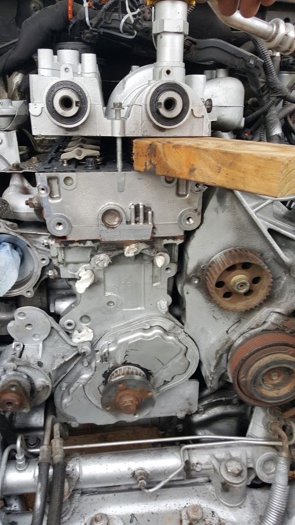
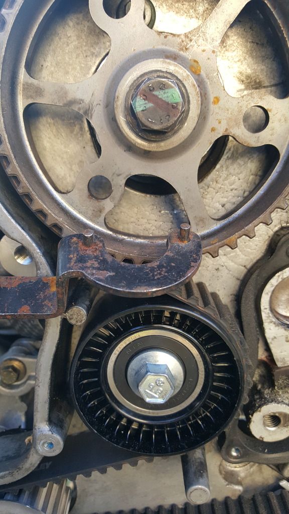
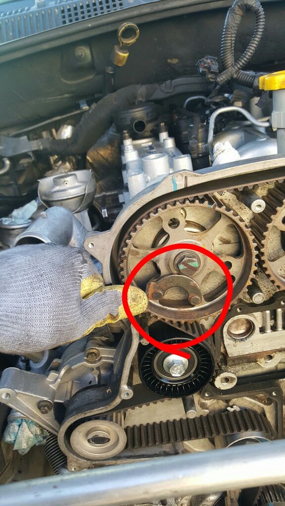
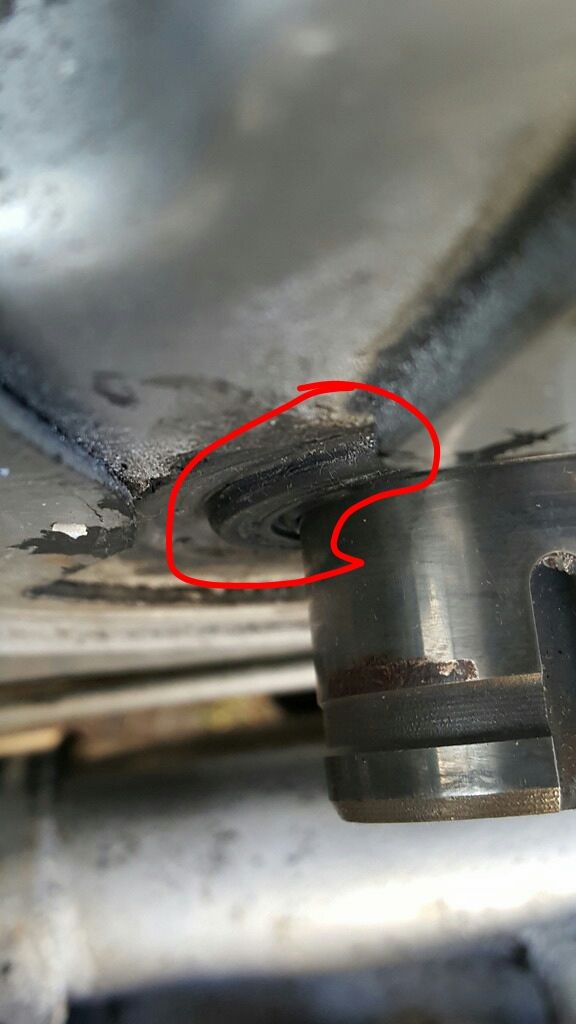
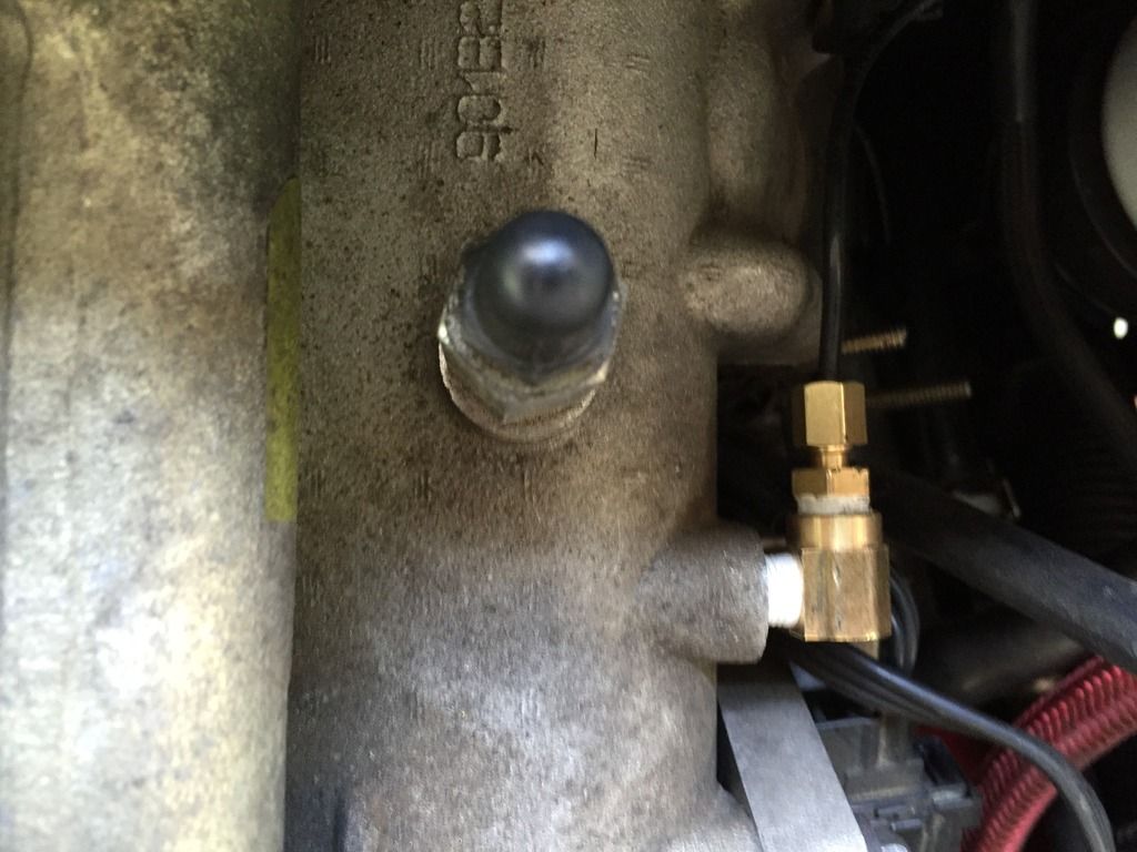
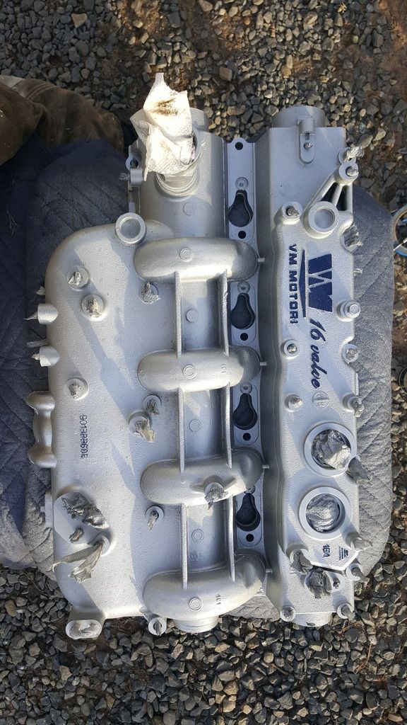
It's an excellent opportunity to prepare for a future boost-gauge upgrade; drill and tap an eighth-inch (1/8th") NPT (aftermarket standard, correct?) threaded-hole into the intake manifold; excellent existing location to tap pictured, just in front of the main intake port. LOCATION AND PHOTO COURTESY OF WWDIESEL: ![]() HEAD/ARP INSTALL: 
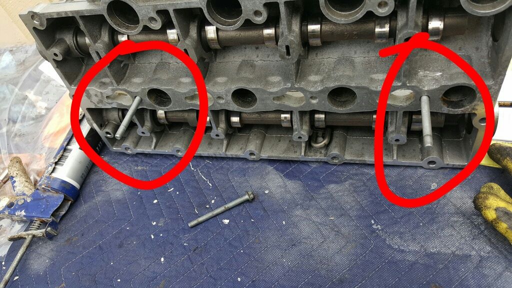
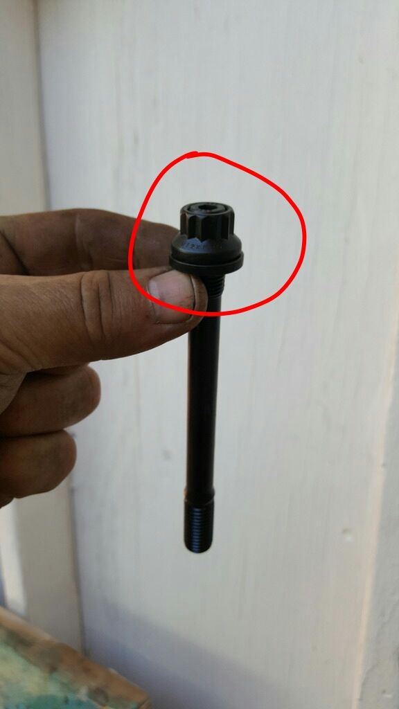
Lightly pre-lube ARPS; - At nut-end (Un-flared, finer threads); - At nut threads; - At both sides of washers. Do NOT lube ARPs at block threads (flared end of stud, coarser threads). "Pre-assemble" studs, washers and nut, threading nut until flush with stud-end: ![]() Then install all 18 stud-assemblies until finger-tight. Proceed to tighten studs in "customary" head-bolt pattern, from center of head to outermost holes in an expanding X pattern. Commence torque sequence. A. 40#; B. 85#; C. During final tightening sequence, torque the inner 10 studs that border the cylinders to 130#, but the remaining outer 8 studs to 125#. NO loosening required between B & C. OPTIONAL: - Apply a light, even coat of preferred gasket-spray (I used copper) to both sides of head gasket pre-installation (wait 'till tacky). - Pre-Soak NEW (of course) Rockers in fresh motor oil bath 
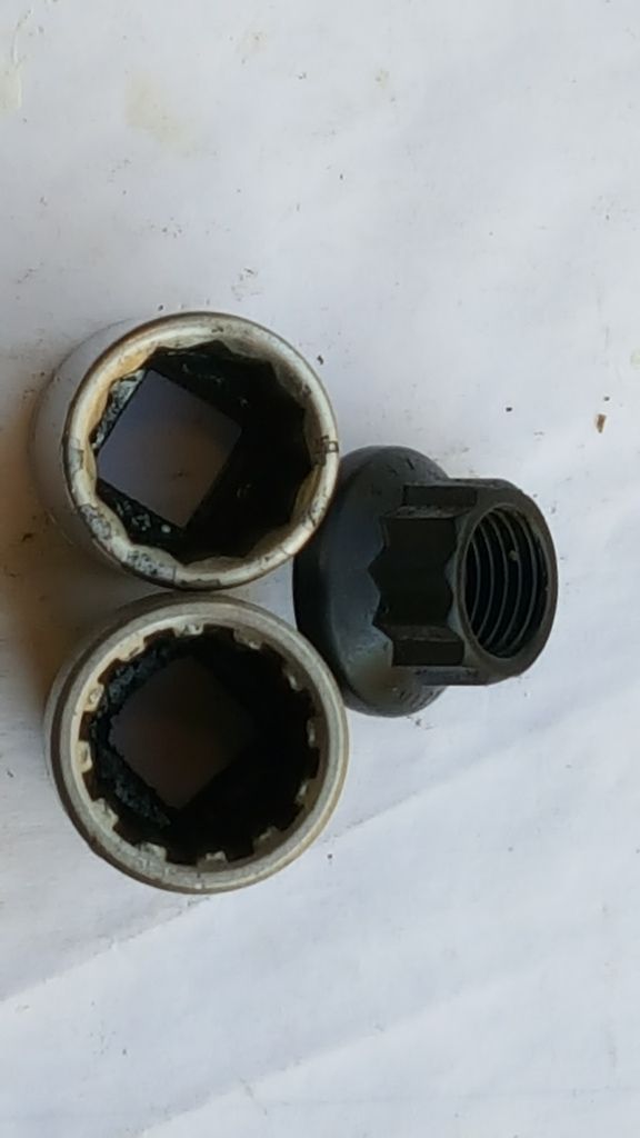
For a far more secure grip on the ARPs' funky 'star' heads, instead of using a 12-point conventional socket consider obtaining either a set of actual star-sockets or these commonly available "square sine wave" sockets (useful in many situations): ![]() 
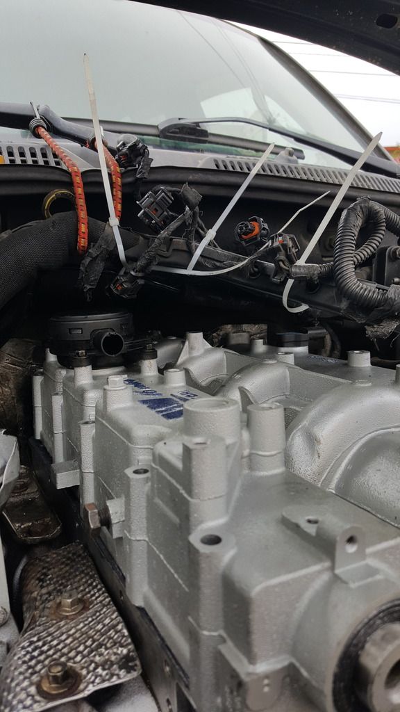
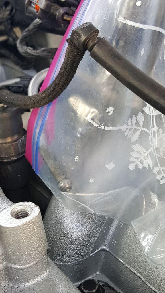
I painted both the valve-cover and tbelt outer cover (don't paint-over your timing marks!!!) with 3 coats of high-temp engine paint and then 3 coats of engine clear-coat (gloss): ![]() ![]() 
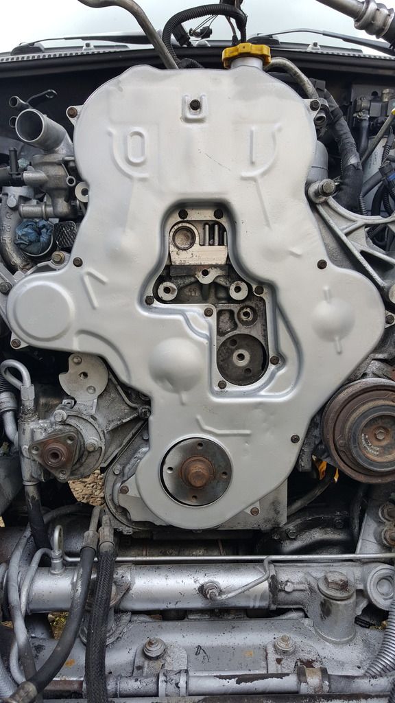
Goofy and bored, assuredly, but it does help with locating leaks, cleaning, and contrasting tertiary parts. 
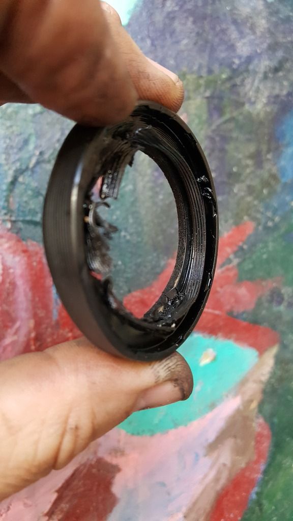
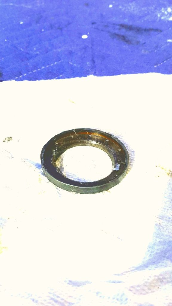
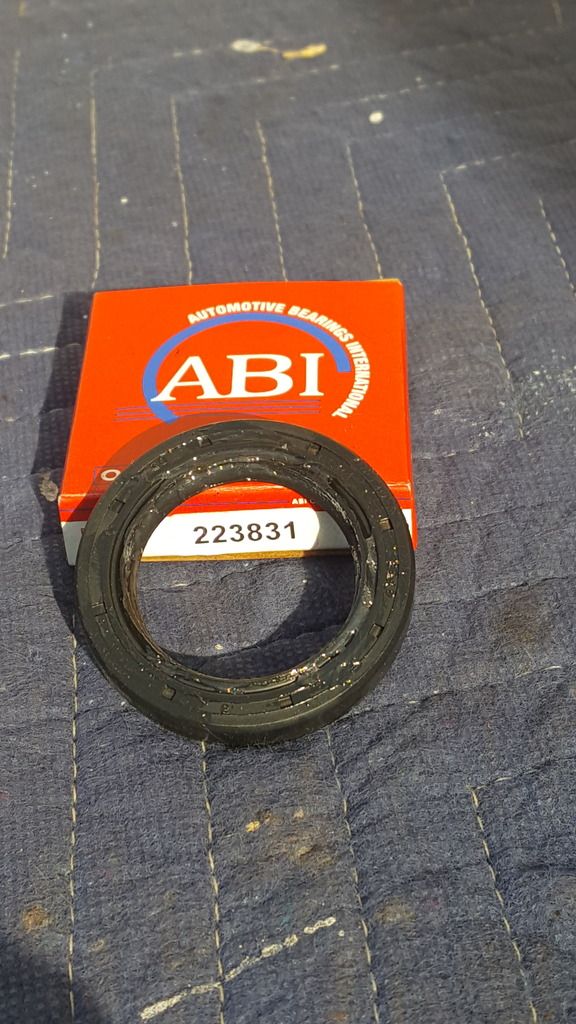
Keywords: cylinder-head replacement procedure procedures sequence, timing-belt replacement procedure and special tools (lol), inferior front oil seal alternative alternatives options, 5/8" coolant hose routing layout locations, bored yet super-cool motor-tattooing, historical relationship between calisthenics and engine reassembly. |
Author: | diesel_guy86 [ Thu Oct 20, 2016 6:54 pm ] |
Post subject: | Re: Valve-lash? Notes from head R&R |
I would not worry about "priming" the lifters. I took all 16 of my lifter/rockers and put them in a gladware container filled with 5w40 synthetic oil. The holes in the lifters are so tiny they need pressure to fill with oil. Just plop them in and go. |
Author: | lacabrera [ Fri Oct 21, 2016 4:47 am ] |
Post subject: | Re: Valve-lash? Notes from head R&R |
I went to the trouble of locking the cam gear to the shafts. I have heard of so many possible slipped gears after a timing belt change that made go with the mod. Its much simpler than it first appears Measure the notch on the cam (might be 4mm) was over a year ago I carried out this work. Hardest part Determine the exact position on the cam gear to drill a 4mm hole to allow a 4mm harden still pin to be inserted. Once the cam sprocket washer and bolt is inserted it holds the pin in place. There is a small amount of play to time exactly but will prevent movement enough to prevent piston/valve contact. |
Author: | geordi [ Sat Oct 22, 2016 1:47 am ] |
Post subject: | Re: Valve-lash? Notes from head R&R |
There is no lash to adjust, that is what the hydraulic lifter is for. As far as oiling them before assembly - I don't do that either, they get pressurized and find their happy place within the first few seconds of operation and automatically take up any slack. |
Author: | xhizzous [ Mon Oct 24, 2016 1:48 pm ] |
Post subject: | Re: Valve-lash? Notes from head R&R |
diesel_guy86 wrote: I would not worry about "priming" the lifters. I took all 16 of my lifter/rockers and put them in a gladware container filled with 5w40 synthetic oil. The holes in the lifters are so tiny they need pressure to fill with oil. Just plop them in and go. After doing a headgasket on my 05 and such on the reassembly..I soaked mine in 15w50 mobil 1 for a few min each when i installed them as well as using some really heavy assebly lube on the cams when I put the valve cover back on. I didnt get to finish and fire the thing up for another week or 2 as I was busy so I figure with the heavier lubricants nothing should have been dry when I had to start cranking on it to bleed the air out of the fuel rail... Changed the oil right before I fired it for the first time and its been running fine since then. I used it to pull a 2wd 02 cummins Ram 2500 that was stuck in my squishy backyard out just last night. .. so probably 6500lbs of truck, no problem |
Author: | Gypsy62 [ Fri Jan 06, 2017 12:03 am ] |
Post subject: | Re: Valve-lash? Notes from head R&R |
I guess this is my personal HG etc. R&R thread, so in spite of months diverted, onward. THE CRD's HYDRAULIC VALVE DESIGN IS ENTIRELY SELF-ADJUSTING; no lash-adjust necessary. What an unbelievably stupid valve-train design. Anyway, here's some notes: - leave the CCV puck OFF the valve cover (VC) until the VC is completely mounted; it obstructs a VC mounting bolt. - zip-tie all the injector plugs out of the way. - remember you have to set the VC gasket onto the head-surface BEFORE you install the new rockers (stupid design). - to help guide VC installation, you can use two of the (10) longer VC mounting bolts but (temporarily) place them through the shorter center holes for abundant prevail. - I should have placed a dab of grease on the loose-end of the rockers to help them "stick" to the top of the valve-stem during installation. Either way, you'll need to visually confirm that none of those stupid bas-turds has slipped-off before tightening the cover (naturally, the far-end ones are most likely to slip during installation #%&@ !!!). I used a 2x4 to prop the front of VC high enough to scope the rockers. - DON'T FORGET TO 'MOUNT' THE OIL DIPSTICK FLANGE WHILE THE VC IS STILL LOOSE: IT WILL NOT FIT ONTO THE AIR INTAKE STUD AFTER VC IS TIGHTENED! - I'm leaving the #1 injector out until all timing alignments are confirmed and secure; it may be handy to be able to easily track TDC with absolute certainty during that process (why not?). Here's pics of how I handled this buffoonery today: ![]() ![]() ![]() ![]() Tomorrow, tbelt & test ...................... |
Author: | olypopper [ Fri Jan 06, 2017 1:18 am ] |
Post subject: | Re: Valve-lash? Notes from head R&R |
Why in the world would you think this is a "stupid valve train"? I'm a mechanic for a living and after I disassembled and inspected mine I have a new found respect for Italian turbo diesels by VM. It's a wonderfully simple design and assembly is very quick and no need for time consuming rocker arm adjustments. |
Author: | geordi [ Fri Jan 06, 2017 2:48 am ] |
Post subject: | Re: Valve-lash? Notes from head R&R |
olypopper wrote: Why in the world would you think this is a "stupid valve train"? I'm a mechanic for a living and after I disassembled and inspected mine I have a new found respect for Italian turbo diesels by VM. It's a wonderfully simple design and assembly is very quick and no need for time consuming rocker arm adjustments. Exactly! I've heard people say that this is the same kind of heavy-duty design as the big trucks get, just smaller. Every design has weak points, but we have pretty well figured out the big ones on these. I can't see where this is a bad design if you do the suggested mods from here. Certainly there isn't anything like it out there. |
Author: | Gypsy62 [ Fri Jan 06, 2017 3:23 am ] |
Post subject: | Re: Valve-lash? Notes from head R&R |
Uh boy, now I've p.o.'d the faithful... No doubt you're a far more qualified tech than I (seriously); but sorry, there's a lot about these engines that leave me asking "Why?" I'm no engineer, but I paid the bills working on Soobs for years. Comparatively, this design just seems fragile -no, it is PROVEN to be more fragile- and I'll take separated cams with shims any day. Granted, experience breeds confidence, and this is my first battle with a 2.8 CRD, so these vehicle-specific procedures are a new challenge. But, from timing belt instead of chain, to woodruff-less cams, to single-lip crank seals, to early TC/Trans failures, to unusually frequent fuel-supply issues... what else am I forgetting here... cheesy window regulators... etc. Add that time after time, in my view one suffers convoluted R&R sequences that reflect poor design coordination. Please keep in mind that I'm still looking forward to thoroughly enjoying my CRD after I've completed the fortifications that have taxed these old bones these past months: ARB-lockers front/rear; ARB front bumper; 2.5" CRD-rated Frankenlift w/JBA UCA's; Head Gasket; Exhaust Valves/seals; Rockers; ARP's; Tbelt/H2O pump/Thermo; Sasq. I&II; Motor Mounts; Kennedy Lift Pump; 11-Blade fan/Hayden clutch; Coolant flush (NOAT fill). More to come... Setting aside that bright future, I come from the school that fidelity does not automatically dismiss criticism: A diesel that falls apart at <150k? That's okay? I absorb that many of these problems are US EGR-related. Still, this beast can be otherwise aggravating. Hopefully, my mood -and overall opinion of the VM 2.8- will buoy after I'm once again chugging down the road. |
Author: | Gypsy62 [ Fri Jan 06, 2017 3:51 am ] |
Post subject: | Re: Valve-lash? Notes from head R&R |
Oh; and please feel free to share any advice or tips regarding the timing procedure. I've read many threads and have a pile of notes, but info from personal experience is always appreciated. Thanks! |
Author: | flash7210 [ Fri Jan 06, 2017 7:17 am ] |
Post subject: | Re: Valve-lash? Notes from head R&R |
The VM R428 valvetrain has a lot in common with many DOHC gasoline engines. As stupid as it seems, its not unique. What IS stupid is how the valve cover/intake manifold also holds the camshafts. I mean seriously. How are you supposed to verify camshaft timing, lift, and duration if you cant see the movement of the valves when the camshafts are assembled? What are we supposed to do, just trust the manufacturer that everything was machined properly at the factory? Thankfully, the VM 2.8L Duramax engine uses a traditional method of holding the cams in the head, with a separate valve cover and separate intake manifold. |
Author: | flash7210 [ Fri Jan 06, 2017 7:29 am ] |
Post subject: | Re: Valve-lash? Notes from head R&R |
Gypsy62 wrote: Oh; and please feel free to share any advice or tips regarding the timing procedure. I've read many threads and have a pile of notes, but info from personal experience is always appreciated. Thanks! Dont use the cheap timing tool set found on ebay. Dont rely on the timing pins to hold the cams while torquing the sprockets. Be careful with the tensioner. Dont strip out the threads. Do install the belt before torquing the sprockets. Do use a tool for holding the cam sprockets and torquing them. Do rotate the engine several times and re adjust the tensioner. |
Author: | Gypsy62 [ Fri Jan 06, 2017 2:01 pm ] |
Post subject: | Re: Valve-lash? Notes from head R&R |
Great. Thanks! I have a note somewhere that for crank/cam/injection pump manual-timing confirmation it requires six rotations to bring the inj. pump 'full-cycle'. X2, Flash. That's precisely what "pushed me over the edge" into tirade-land; taking almost two hours to set the VC/intake/cam assembly. Sure, IF there's a 2nd time (I frigging hope not) it would likely take 1/2 hour, but the anxiety induced by blindly navigating 16 precariously-teetering rocker-lips... yes, please; separated cams. Oh; and the 2nd time I'd know to leave the CCV puck off, install the VC gasket BEFORE installing the rockers, and capture the oil dipstick flange BEFORE snugging the VC. The required sequence to R&R the front axle/diff/half-shafts/ suspension components requires a map hidden in a cave under Mt. Fuji and the Freemason secret handshake! Re convoluted R&R procedures, I'm painfully aware that applies to ALL makes and models. You'd think that after 100-plus years of automotive engineering that there would be diligent coordination of systems-design anticipating future service procedures. It's probably no accident; = added corporate profit at their service departments... |
Author: | Mountainman [ Fri Jan 06, 2017 2:07 pm ] |
Post subject: | Re: Valve-lash? Notes from head R&R |
Yeah, why spend money on good design that just shorts then on more labor charges... They'd lose two fold ![]() |
Author: | GordnadoCRD [ Sat Jan 07, 2017 3:23 am ] |
Post subject: | Re: Valve-lash? Notes from head R&R |
It will also save you time to connect the proper electrical plug into the Fuel Pressure Control Valve at the back end of the rail BEFORE you put it in final place and secure it. Once you get the rail in there, it's a royal witch reaching it and reversing the plug to get it in. It may also lessen confusion regarding which plugs are for sensors and which for injectors. |
Author: | Gypsy62 [ Sat Jan 07, 2017 4:28 am ] |
Post subject: | Re: Valve-lash? Notes from head R&R |
- Before re-installing the cam and crank pulleys during tbelt R&R, it's customary to replace the three front oil seals. Review notes on sourcing a quality double-lipped front crankshaft oil seal at tail. - Remember to leave the cam-sprockets LOOSE until the tbelt is on, the crank and inj. pump are properly aligned, and the belt is properly tensioned. I didn't exactly approach the timing procedure 'by-the-book'. It's crucial to remember that since the cam-sprocket bolts are loose during the entire timing-belt installation/tensioning process, THE ONLY RELATIONSHIP THAT MATTERS IS THE CRANK/INJECTION-PUMP ALIGNMENT. The tbelt installation videos on youtube are only somewhat helpful. Robot-chicken advises that you can press the tbelt on without removing any components. However, I wasted 20 minutes wrestling with the tbelt before finally deciding to remove the crank locking-pin as well as the timing-tensioner's bolt thereby making it quite easy to properly thread the tbelt. After again confirming that the crank and injection pump were correctly aligned, it was not difficult to use a small pry-bar to gently leverage the tensioner until it's bolt could be easily reinstalled without cross-threading or excessive resistance. This may or may not have been possible with the crank-pin still set, but as long as you have accurate alignment marks to observe on the crank pulley & case, being able to rock the crank backnforth can be helpful. Cheap circlip tool for leveraging the timing tensioner: ![]() After the tbelt tensioner is adjusted, tighten the cam-bolts. My version of the cam-lock tool: ![]() Either a saw-blade or grinder-disc wrench. Ideal? Hardly, but it seemed to provide an adequate counter-force to a torque-wrench set at 80#. I was agitated about leveraging force against the sprocket-material, but 80# is not gargantuan force. Placing one of the tool's studs into a sprocket-hole, I did my best to apply an equal counter-force to relieve pressure on the cam lock-pins. It is an imperfect solution, but frankly it "felt" quite workable; similar to doing a "push-up", you can tell when you're favoring one arm over the other and equalize forces. Depending on your own body-weight, strength, and mechanical experience/confidence, 80# is not a huge load to counter. I'm 200#, so counter-forcing much more than 80# (x2 arms =160#, etc) would have been a different story: ![]() ![]() After torqueing the cam bolts, I removed the old cam marks (with brake-cleaner on a rag) and applied fresh alignment marks. Then, I removed the cam timing-pins and made 12 clockwise crank-rotations to confirm the crank-cam timing 6x and the crank/injection-pump timing 2x. Tomorrow will tell. - Thanks to Flash for answering my separate post with questions regarding the tensioner. If I understand correctly, it is normal: A. That it requires very little torque to adjust the tensioner. B. That the spring-loaded tensioner allows for its calibration-tab to flex a great deal when the tbelt is being manually rotated (seemed sketchy to me, but nope). - there's a Russian youtube 2.8 CRD tbelt install vid that appears to show the crank lock-pin being inserted on the LEFT side of the block (?). FRONT CRANK SEAL: I replaced the front crank seal. The old seal was a 'standard' double-lip seal and seemed very well made (and it didn't leak). However, although the two CAM oil seals were entirely adequate, the replacement front-crank seal supplied by IDPARTS is an inferior single-lip seal; it may actually be the current OEM part, listed as Part #5179633AA (it is 55x40x6mm wide). I substituted a dual-lip Nitrile seal, ABI Part #223831 (55x40x8.75mm). I always pre-lube oil seals' I.D. using vaseline, and coat the O.D. with ultra-black sealant (can't hurt): OLD DOUBLE-LIP SEAL: ![]() IDParts, OEM (?) SINGLE-LIP SEAL: ![]() ABI DOUBLE-LIP SUBSTITUTE: ![]() CAUTION: There is only 9mm between the internal crank mounting-bolts and the outer-edge of the block; but then there's only 2mm between the outer-edge of the block and the inside-edge of the crank-pulley. Combined, that means that the 8.75mm-wide ABI seal has a total of 11mm of space to fit within. Therefore it is imperative to leave 1mm of prevail when installing the ABI seal. Actually, I set it slightly further-in after this pic: ![]() You may prefer the premium-grade dupont 'Viton' alternatives: "Colonial Seals" 55x40x8mm Viton seal for $28, Part #A1048; European Viton supplier "Kramp" Part #40558CBVP001. CONFIRM SIZE/FIT PRE-PURCHASE: 55x40x 6-9mm wide. |
Author: | Gypsy62 [ Sat Jan 07, 2017 11:43 pm ] |
Post subject: | Re: Notes from Cylinder Head R&R |
CON'T: Cranked like a champ, no start, timing confirmed holding spot-on at crank/inj.pump/cams. Unfortunately, I have to t-shoot a fuel-supply issue. She's been dormant for four-months, so... 3/4 tank, the fresh Kennedy pump is humming, but nothing to the fuel head. MORE FUN! Question: aside from pending fuel-supply issue, what systems MUST be reconnected for 30-second test-run post-tbelt install??? A. All injectors replaced/connectors snug. B. Injection pump installed, timed, wired. C. Glos installed & connected. D. ALL of the topside solenoid/sensor connectors snug. ( F. Oil/filter changed) Other? While cranking, I was thinking of air-bleeding the fuel rail by feeding the #1 injector line into a big ziplock bag, tubing the return line to a container. Bad idea? ![]() I also took the time to update the ground that has given others trouble. The existing bolt needed to be cut off, grinder duty. If your bolt won't loosen it's faster to just drill a fresh ground location adjacent to the old hole; I found the space just to the right ideal (in the close-up, you can see the old bolt-stub just left of the fresh hole). I swapped an abrasive-disc onto my grinder to clean both the unified cables' copper ground-plate as well as to remove the OEM paint and expose raw metal on the body-mount location. Everything gets Electro-Salsa to dress the wounds and prevent rust on fresh metals: ![]() ![]() Actually, after viewing these pics, I think I'll run an additional wire from the new bolt directly to the battery-terminal ground; short and sweet. No such thing as too many grounds. Predictably, this prolonged R&R has consumed the fourth fuel-rail return-line retainer clip. Hopefully, some universal clip will suffice. If not, I'm thinking a proper-size safety-pin could work, "hugging" the circular return-line fitting... |
Author: | joe_ [ Sun Jan 08, 2017 12:44 am ] |
Post subject: | Re: Notes from Cylinder Head R&R |
Gypsy62 wrote: Predictably, this prolonged R&R has consumed the fourth fuel-rail return-line retainer clip. Hopefully, some universal clip will suffice. If not, I'm thinking a proper-size safety-pin could work, "hugging" the circular return-line fitting... I could see a safety pin doing the trick, at least temporarily. idparts stocks the clips, but they aren't cheap. Some people have bought replacement clips for a Duramax; apparently they use the same return line fittings. If you google "duramax fuel return line clip", they come up. Edit: clarified return line fittings |
Author: | Gypsy62 [ Sun Jan 08, 2017 1:07 am ] |
Post subject: | Re: Notes from Cylinder Head R&R |
Stellar info! Thanks! |
Author: | Gypsy62 [ Tue Jan 10, 2017 3:10 pm ] |
Post subject: | Re: Notes from Cylinder Head R&R |
YEEEEE-HAAA! Test-running like a champion! I also now believe that five months ago I may have misdiagnosed my previous running issue; my old injectors may have been okay and it may have just been fuel-starved. Not 100% sure, but my previous tank-top fuel-line 180-turn setup may have been crimping with the tank snug. I'm installing hard fittings instead to insure flow. Still very PO'd that my near-new Kennedy seems to be toast. |
Page 1 of 4 | All times are UTC - 5 hours [ DST ] |
Powered by phpBB © 2000, 2002, 2005, 2007 phpBB Group http://www.phpbb.com/ |