LOST JEEPS
http://www.lostjeeps.com/forum/phpBB3/

04 KJ roof Rack: Preliminary 3D design
http://www.lostjeeps.com/forum/phpBB3/viewtopic.php?f=59&t=40633
Page 1 of 2

Author:  sandman [ Wed Feb 25, 2009 10:29 am ]
Post subject:  04 KJ roof Rack: Preliminary 3D design

I've recently started playing around designing a roof rack for my KJ. I found a program online called Google Sketchup. Its working great for this project, although I'm not a pro at it.

I do alot of surf fishing so the rack is for carrying long (12ft) fishing rods and sandy stuff like chairs, wader bags and misc. stuff. Some of the features I wanted were shovel mount, backup/aux rear lighting, rod holders and an awning to be able to get out of the summer sun. I didn't want the awning to attach to the ground because we often move our vehicle short distances up and down the beach with the tide.

This is a preliminary design but it will give you an idea of what I'm thinking. I plan to use 3/4 EMT electrical conduit with screw couplings for assembling the upper and lower hoops. I know those couplers only pince the conduit so I plan to through drill the conduit and possible use JBweld to add strength and some waterproofing.

Let me know what you think and if you have any suggestions. BTW, I know some parts aren't "attached" in the pics and I also need to come up with some king of floor for the rear portion.


Image

Image

Image

Image

Image

Author:  riptricket [ Wed Feb 25, 2009 1:21 pm ]
Post subject: 

WOW GREAT JOB!!!
How di you get that Jeep on there?

Author:  0311_DoC [ Wed Feb 25, 2009 1:31 pm ]
Post subject: 

that looks like its gonna turn out great

Author:  Boiler [ Wed Feb 25, 2009 1:52 pm ]
Post subject: 

Looks great!

1) How do you plan on holding down the tips of the fishing poles?
2) Just a suggestion, but I would make the bottom bar of your fold out arms run on an angle and tie into the top bar, instead of running them parallel. You'd get a better truss type effect and it would be more rigid IMO.
3) Where did you get the jeep model and can I get a copy? I need one desperately for things I'm working on right now and haven't seen anything worth anything online.

Author:  sandman [ Wed Feb 25, 2009 1:59 pm ]
Post subject:  sketchup

If you download the "google sketchup" software there is a place called 3D warehouse. go there and you can download the 3D model. its all free. Once you get the KJ model you can explode it into seperate parts, delete things and add as you like. Its really helpful to visualize how things will look. The warehouse has 1000's of parts from nuts and bolts to lights and just about anything.

again, I've had the software about 4 days and came up with this rack, there's tons of videos on youtube to help start using the software. It just takes a little time to get used to modeling in 3D if you've never done it.

Author:  sandman [ Wed Feb 25, 2009 2:01 pm ]
Post subject: 

Oh, and the rod tips are held in place with locking ski racks, mounted on the middle support but I may move them to the very front of rhe rack. Its still in the concept stage.

Author:  XC204 [ Wed Feb 25, 2009 2:12 pm ]
Post subject: 

Now thats nice!!!! not a copy of any thing on the market. The internal dim of 3/4 EMT is .824" I think you could cut some 2.5" stubs of 3/4 EMT take a slice out of them lengthwise with a hacksaw or an angle grinder and internally sleeve your joints would be sturdier and smoother looking still screw or rivit each side.

Author:  sandman [ Wed Feb 25, 2009 3:19 pm ]
Post subject: 

XC204, I like how u think, never thought of sleeving it but that just might work, hanks. Thats why I love this site, always more that one way to skina cat.

Author:  Li-bah-tee_13x [ Wed Feb 25, 2009 3:47 pm ]
Post subject: 

i tried to use that sketchup...jeeze thats hard...how do you take parts off of the models? :?: great rack idea by the way... 8)

Author:  sandman [ Wed Feb 25, 2009 6:22 pm ]
Post subject: 

On the things I've downloaded the models pieces are grouped into assemblies and sub-assemblies. Just select the model (a box lights up showing whats selected) and under the edit-group menu pic explode. It really helps if you thinkin groups of parts when working with the program.

again, there's tons of tutorials on youtube.

Author:  Li-bah-tee_13x [ Wed Feb 25, 2009 6:47 pm ]
Post subject: 

ok...i think i figured that out..but one more question...how did you make that tubing?...for the basket?

Author:  sandman [ Wed Feb 25, 2009 7:00 pm ]
Post subject: 

Its done with the "follow me" tool. Honestly, that was the hardest thing to figure out, even with the help of the online videos. It took me about an hour to get the hang of it but I'm a slow learner.

Author:  Li-bah-tee_13x [ Wed Feb 25, 2009 7:07 pm ]
Post subject: 

ok..thanks for the info, im plugging away at it. i foresee countless hours in front of the monitor trying to get the hang of this 3d stuff... Im pretty good at photoshop, but this is the next level. please keep me up to date with anything new you make..im hooked. :shock:

Author:  XC204 [ Wed Feb 25, 2009 8:06 pm ]
Post subject: 

Hey if you bend just two hoops for each bar I think you can get away with only 2 seams / frame section they can be hidden behind the center tie plates.

Author:  libby [ Thu Feb 26, 2009 9:07 pm ]
Post subject: 

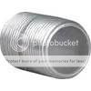
Where you find the conduit and accessories you will also find a steel, tapered, externally threaded male coupler. Lightly grind the threads and you will have a serrated internal sleeve to join the 3/4" conduit. Pressure fit + JB weld might just hold. Personally, I would (did) weld it.

Image

Author:  sandman [ Thu Feb 26, 2009 11:29 pm ]
Post subject: 

Thanks for the suggestion Libby. I've been kicking the idea around with a few people, one of which is a welder. He's going to buy a piece of 3/4 EMT and take a shot at welding it, he's never worked with the stuff before. Depending on his success I may prefab as much as I can and have him do it. Im trying to keep the cost as low as I can so I dont think threaded couplers are the way to go, at least for me. If I dont get it welded Im going to give the internal sleeve idea a shot with JBWeld and some screws.

Hope to pick up the materials next weekend and get started. If theres interest I will take pics and post progress. Also, I think I've decided to make the topslightly smaller in length so I can add an angled fairing to the front. Just not sure how much of an angle there should be...anyone have ideas?

Author:  0311_DoC [ Fri Feb 27, 2009 12:18 am ]
Post subject: 

sandman wrote:
If there's interest I will take pics and post progress. Also, I think I've decided to make the top slightly smaller in length so I can add an angled fairing to the front. Just not sure how much of an angle there should be...anyone have ideas?


oh there is interest ... take lotsa pics :wink:

Author:  Maximum Carnage [ Fri Feb 27, 2009 11:30 am ]
Post subject: 

I’ve got to say you are doing a great job with this 3D design and yes take as many pics as possible, we are very much interested. Google sketch-up is the next software I’m downloading. The fun and ideas we can come up with for front/rear bumpers.

Author:  tommudd [ Fri Feb 27, 2009 12:34 pm ]
Post subject: 

angled in front
I would say 3 to 3.5 inches should be good, anyhting less would still be to straight up

Author:  XC204 [ Fri Feb 27, 2009 1:49 pm ]
Post subject: 

You should go to HD or Lowes get a 3/4 inch bender and skip the "Sparky" Bending conduit is easy and you end up with a bender at the same price.

Page 1 of 2 All times are UTC - 5 hours [ DST ]
Powered by phpBB © 2000, 2002, 2005, 2007 phpBB Group
http://www.phpbb.com/