I have finally finished my light bar/CB antenna mount and have installed the lights and wiring. The lights I installed are
Hella 500's with 4x55w H3 light bulbs and the CB antenna is a ST-4 48" Tiger antenna from
Everhardt on a spring base.
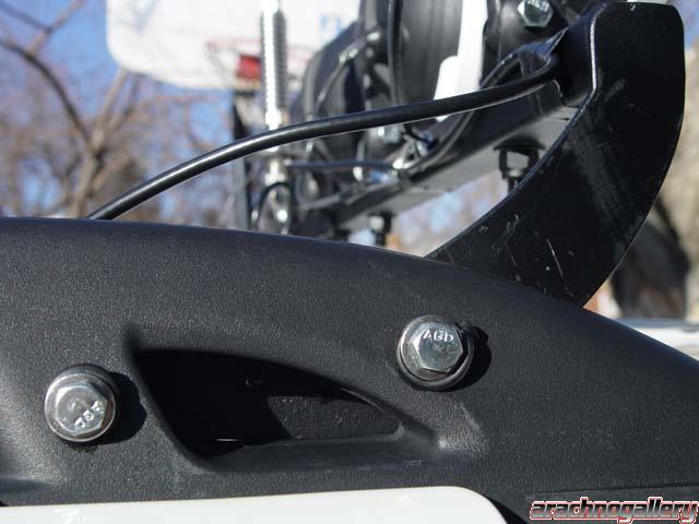
The rack is constructed out of 1" diameter 1/16" thick square steel tubing welded to brackets cut from 3/16" mild steel. Each bracket is attached to the front of the stock roof rack brackets by 2-2x1/4" bolts with nylock nuts. Each bolt goes completely through the composite roof rack bracket. You might be wondering on the strength of the composite. The composite material of the roof rack brackets is between 3/16" and 1/4" thick and quite strong. I can use the light bar as a hand hold that seem to be as sturdy as the stock roof rack. Regardless it is plenty strong to hold 4 Hella 500's and a 48" CB antenna on a spring mount.
Anticipating a near future upgrade; I wired the system to handle 4x100w H3 light bulbs. I used a 30A relay and 15 amp fuse for each individual light circuit instead of one relay for each pair of lights as they come with in the package. I wired a seperate fuse block with six circuits for the lights and relays and mounted it to the steel support panel of the dash access under the steering wheel. I ran 2-10 gauge braided power supply wires directly from the battery to the fuse block so that it will enable me to run the lights whether the key is in the ignition or not. The remainder of the wiring is all in 14 gauge braided wire (not solid) The steel support panel and the lightbar were grounded to the chassis using braided ground wire and suitable mount points. In the case of the dash ground strap I attached it to a ground bolt under the dash where some of the stock electrical system is grounded. The roof rack ground straps are run from eack light bar mounting bracket to the roof with self-tapping screws. Proper grounding of the light bar is critical for proper operation of the lights as well as the CB. In addition to the 4-15 amp light circuits; there is one 10 amp circuit for the relay operation and light switches which are lit themselves. The relay control circuit and switch lights are grounded to the grounded support bracket mentioned above.
The wires for the lights and CB antenna run down the channels on either side formed by the door seal at the top of the door to where the hinge is and then into the dash through the fuse panel or access panel on either side of the dash. Light wires down the driver channel and CB antenna wire down the passenger channel.
The upgrade to the high wattage bulbs is easy as the 100w bulbs only run $5-6 a piece. I do plan to upgrade my alternator first from the 130A alternator to a 160A alternator that Jeep/DC also makes for the Liberty. The system will certainly need the extra current capacity.
I tested the whole system out and ran the Headlights (55w), Upgraded foglights (65w) and all 4 lights on the lightbar (220w) it all seems to work well at this stage. The system is controlled by two lit toggle switches mounted in the dash on the small removeable dash strip to the left of the steering column. One switch for the outer pair and the other for the inner pair of lights.
If anyone would like a template of the 3/16" steel mount brackets; you should just be able to print out the photo of the template below and adjust the printer scale/zoom so that the 1" scale line in the image prints out 1" long. From there everything should be about the same measurement as it is in the photo. Note: I cut the brackets from a 3/16" thick by 3" wide steel flat I purchased at Home Depot. You can carefully position the template along the three inch wide steel to get it to fit just perfectly if it is in the same general orientation as the image on this post.
Full Package.

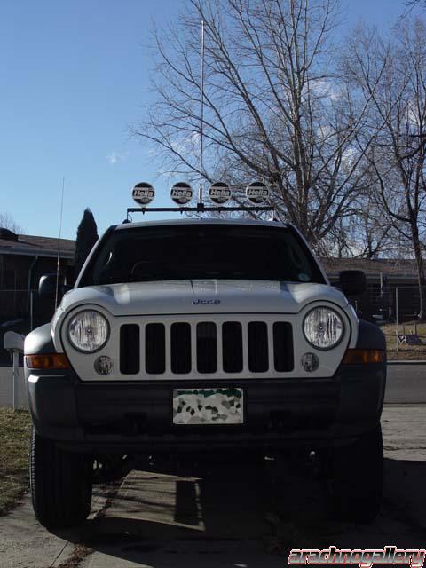
Front View.
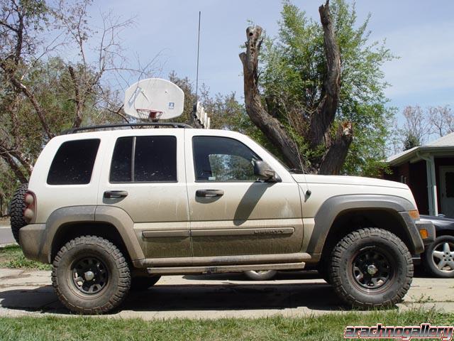
Side View.
Bracket Mount Closeup.
Bracket Gound Point Closeup.

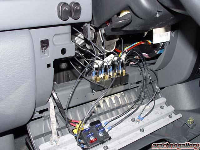
Electrical Closeup. In this last shot you will see the ground strap on the left attached to the steel support of the dash panel which runs to a stock ground bolt on the chassis under the dash on the left. Just to the right of the ground strap are the two red 10 gauge power supply wires coming directly from the positive (+)battery post. The power supply wires attach directly to the 6 circuit fuse block where you can see the four 15 amp light fuses and the 10 amp relay control fuse. The two oval, lighted, on/off switches can be see at the top of the photo mounted to the small grey removeable dash panel just above the fuse panel. Near the center of the photo you can see the 4-12v/30 amp relays for the light circuits. Lastly, you can see to the right of the fuse block, the grounds for the relays and the switch lights. I don't have the inclination (aka too lazy) to draw up the electrical circuit for it all but I do have it all in my head if anyone has any questions.

Some wiring installation and completion detail shots.
Here is a template for the light bar brackets.

John
];')