2006 Liberty CRD and 2005 Passat - ECM Glowplug Control Signal Issue, Arduino Solution
I rarely post to forums, but this is such an unexpected problem I feel I should share.
We have both a 2005 Passat 2.0L TDI and a 2006 Jeep Liberty 2.8L CRD. Two completely different vehicles, with the same symptoms and the same root cause. They both developed difficulty in starting in cold weather, noticeable below 0 celsius, and progressively harder as it gets colder. No error codes.
I went through quite a lot of trouble to find this, but both vehicles use Bosch glowplug control modules (GCM) and while they weren’t the problem, the pulse-width modulated (PWM) signal from the engine control module was.
I’m a retired electronics technician, so I’ll list the info I have. With a Fluke DMM, the Passat glowplug voltage would be about 4.1Vdc, 5.7A for about a 13 second cycle after you turn the key. This was the same for all glowplugs. BTW, I must state that glowplugs or any heating element like them, say in a stove or hot water tank, do not get weak. They’re either good or they’re not, like an incandescent light bulb. And they should glow red brightly when you bench test them, something I didn’t know, though it seems obvious now.
The Jeep glowplugs are rated for 7Vdc. The glowplugs show a 11.5Vp-p pulse at 31hz with a 38.6% duty cycle. Far too little, you barely see it glow at all at the end of a few 14 second cycles with your hands cupped around it. 7 volts is about 62% of a 12V battery, so you should see a pulse duty cycle of about 62%. That is, the glowplugs should be on 62% of the time, not the 38% I was seeing. If I connected the glowplugs to the battery through some resistance wire to drop the voltage to 7V, the Jeep started without difficulty. And you can imagine what fun it is to troubleshoot this at very cold temperatures.
The GCM is a Bosch# 0281 003 034, Chrysler#56044671AC. The nine leads are as follows:
1-4 Glowplug leads
6 Switched 12V from ASD relay
7 Ground
9 Data out to the ECM
11 Always-on 12V
10 Control signal from the ECM
Inside the GCM there’s one main IC, an ST Microsystems L9524 glowplug controller and four ST P85NF55L MOSFETs that do the actual pulsing of the glowplug voltage. These are obsolete parts but you can still find the datasheets online. After study of the datasheets the input signal from the ECM will be used as a clock for the Data Out line and the input signal pulse should be the inverse of what you want on the glowplugs. So I connected the '10' input to a separate PWM signal from an Arduino circuit and found the glowplugs were now getting the correct voltage, ruling out the GCM as the source of the trouble. For the Passat, since I had the ECM open anyway, I traced the glowplug control signal directly to a Bosch#30554 controller IC. I couldn’t find a datasheet for this one, but I found some replacements available on Aliexpress and others. This is about a 64-pin chip though, so clearly it controls more than just the glowplugs, likely the injector solenoids as well. And because of that it’s likely programmable for timing and the number of cylinders. If replaced, it’s possible I might be able to program it via the Rosstech VSDS, but it may be programmed separately and without information on it I really can’t take that chance. And of course replacing the ECM on either vehicle would be far too expensive.
So as an alternative, I created a low-cost Arduino circuit that inputs the PWM signal from the ECM, synchronizes a new correct PWM signal to it, then outputs it to the GCM.
Our Jeep Bentley manual outlines a control strategy based on the coolant temperature as follows:
Coolant
Temp Wait-To Start Pre-Heat Post-Heat
"Key ON" Lamp "ON" (s) GlowPlugs on (s)
-30C 10 SEC. 35 SEC. 200 SEC.
-10C 10 SEC. 23 SEC. 180 SEC.
+10C 1 SEC. 21 SEC. 160 SEC.
+30C 1 SEC. 20 SEC. 140 SEC.
+40C 1 SEC. 19 SEC. 70 SEC.
+70C 1 SEC. 16 SEC. 20 SEC.
This may not be the way the Jeep was actually programmed since the dashboard glowplug indicator has no bearing on the preheat time and the operator would have no clue to pause for that time before turning the key. So I have an LED on the dash that the Arduino flashes when the key is turned and glowplugs are started. It will remain flashing for the preheat period, then stays on steady for the post-heat period. So the operator knows to wait until the flashing stops and it’s on steady before starting the engine. The times in the chart may be overkill. You don’t really need 20 seconds of preheat to start it at 20C, but better too much preheat than not enough.
I happened to have some small boards with an ATTiny85 and a MCP9808 temperature sensor, but any temperature sensor would do. The temperature rating of all the parts made it OK to strap the circuit board to the coolant hose in order to sense the temperature, but one could use a remote sensor like a DS18B20 and have only it strapped to the coolant hose. You’d have to modify the code to suit.
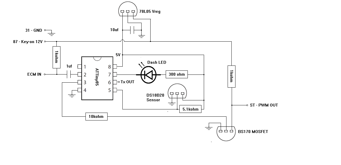
Installation: Cut the wire to the GCM ‘10’ terminal, connect the end that goes to the ECM to ‘ECM IN’ in the circuit below and the end that goes to the ‘10’ terminal connect to ‘ST - PWM OUT’. Splice the wire going to the 6 terminal so it goes to both the GCM and Arduino circuit ’87 – Key-on 12V’. Splice the ground to both as well. Add an LED to the dashboard and run leads to the Arduino circuit connections. Best to make all connections plug-in so you can bench-test the circuit if anything goes wrong.
The schematic is as follows:
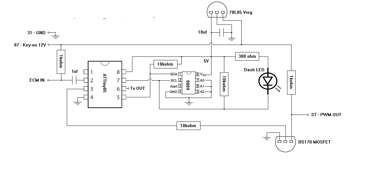
There is more information in the comments of the code below. The pulseIn() function is sufficient to synchronize the output PWM signal with the ECM, so the ECM can still read the diagnostics from the GCM.
The terminal ‘Tx OUT’ is a diagnostic serial connection that will output the temperature from the sensor, the corresponding times from the interpolated look-up table and indicates Preheat, Posthead and Done when it finishes. After this, the Arduino will stop the PWM output, which will turn off the glowplugs, and then enter sleep mode. In order to read the serial output you’d need a serial converter like the FTDI232 or CH340 that many Arduinos use and a PC with Hyperterminal or just use the serial monitor in the Arduino IDE.
The Jeep code is as follows:
Code:
/* To emulate the ECM glowplug control which now is insufficient to start the engine in cold weather.
* If ATTiny has been used before, burn bootloader first just in case.
* Use 1MHz internal clock source. 8Mhz is 8x too fast for this timer setup.
*
* Glowplug PWM is only 38.6% duty cyle (32hz) for 14sec and barely glow if you cup your hands around it.
* 4.1V avg at 5.7A. Glowplugs are rated 7volt.
*
* A 62% PWM signal to the bs170 mosfet below results in a 38% duty cycle to the glowplug module,
* which then results in 62% PWM glowplug drive. 62% of 12 is 7.4V
*
* The ATTiny/MCP9809, clipped to a coolant hose, is connected to the Jeep's glowplug control module.
* Powering it from the AutoShutdownRelay terminal that goes to 12Volts when the key is turned on.
* A 5V reg of course for the Arduino. The arduino will read the coolant temperature via the MCP9808.
* Based on the temperature, it will drive the glowplugs for the pre-glow time from the chart while flashing an LED indicator.
* After the pre-glow elapses, the LED goes solid, and it continues to drive the glowplugs for the post-glow period, then turns off.
*
* Uses the ATTinyCore by Spence Konde
*
* Use 1MHz clock source. 8Mhz is 8x faster!
ATtiny85 has 3 PWM outputs. They are located on pins 0, 1 and 4
Attiny85 and MCP9808 have max temps of 125degC (257degF). The jeep has a 176F, 80C thermostat.
MC78L05 5Vreg max 120C and BS170 Mosfet max 150C
Jeep service outlines the glowplug durations vs temperature:
Coolant
Temperature Wait-To Start Pre-Heat Cycle Post-Heat Cycle
"Key ON" Lamp "ON" (s) GlowPlugs on (s) (s)
-30C 10 SEC. 35 SEC. 200 SEC.
-10C 10 SEC. 23 SEC. 180 SEC.
+10C 1 SEC. 21 SEC. 160 SEC.
+30C 1 SEC. 20 SEC. 140 SEC.
+40C 1 SEC. 19 SEC. 70 SEC.
+70C 1 SEC. 16 SEC. 20 SEC.
Programming
ATTiny85
MOSI PB0 (Pin5)
MISO PB1 (Pin6)
RESET PB5 (Pin1)
CLK PB2 (Pin7)
Vcc
Gnd
MCP9808 ATTiny85 DIP
Pin2 Pin7 (SCL, PB2)
Pin1 Pin5 (SDA, PB0)
Physical Pin 3 (PB4) output via a 100k resistor to the mosfet center terminal.
|---------------------> to glowplug module 'control' input light-blue/brown wire (labeled ST)
| BS170
| MOSFET
12V >-------VVVVVVVV---|----| | |----------< GND
1k |
PB4 >-------VVVVVVVV-----------|
10k
*/
#include <Wire.h>
#include <avr/interrupt.h> // library for interrupts handling
#include <avr/sleep.h> // library for sleep
#define SDA_Pin 0 //0 refers to PB0, pin 5 on the ATTiny85 DIP
#define SCK_LED_Pin 2 //2 refers to PB2, pin 7 on the ATTiny85 DIP
#define PWM_Pin 4 //4 refers to PB4, pin 3 on the ATTiny85 DIP
#define TX_Pin 1 //1 refers to PB1, pin 6 on the ATTiny85 DIP
#define ECM_Pin 3 //3 refers to PB3, pin 2 on the ATTiny85 DIP
#define ArraySize 6
//software serial used on LED_Pin to confirm temperature measurements and look-up table, but then not used.
//software serial is also incompatible with the PCINT vector ISR
#include <SoftwareSerial.h>
// software serial #1: RX,TX. TX>RX, RX>TX
SoftwareSerial portOne(-1, TX_Pin); //transmit only, so -1 to not use a pin for rx.
#ifndef cbi //to turn off ADC
#define cbi(sfr, bit) (_SFR_BYTE(sfr) &= ~_BV(bit))
#endif
// Device address
const int MCP9808_Address = 0x18; //address pins should be physically tied to VCC or ground
//with address pins floating a scanner sketch reports address 0x1F
// Make sure the sensor is found, you can also pass in a different i2c
// address with tempsensor.begin(0x19) for example, also can be left in blank for default address use
// Also there is a table with all addres possible for this sensor, you can connect multiple sensors
// to the same i2c bus, just configure each sensor with a different address and define multiple objects for that
// A2 A1 A0 address
// 0 0 0 0x18 this is the default address
// 0 0 1 0x19
// 0 1 0 0x1A
// 0 1 1 0x1B
// 1 0 0 0x1C
// 1 0 1 0x1D
// 1 1 0 0x1E
// 1 1 1 0x1F pins floating
//#define MCP9808_I2CADDR_DEFAULT 0x18 ///< I2C address
#define MCP9808_REG_CONFIG 0x01 ///< MCP9808 config register
#define MCP9808_REG_CONFIG_SHUTDOWN 0x0100 ///< shutdown config
//#define MCP9808_REG_CONFIG_CRITLOCKED 0x0080 ///< critical trip lock
//#define MCP9808_REG_CONFIG_WINLOCKED 0x0040 ///< alarm window lock
//#define MCP9808_REG_CONFIG_INTCLR 0x0020 ///< interrupt clear
//#define MCP9808_REG_CONFIG_ALERTSTAT 0x0010 ///< alert output status
//#define MCP9808_REG_CONFIG_ALERTCTRL 0x0008 ///< alert output control
//#define MCP9808_REG_CONFIG_ALERTSEL 0x0004 ///< alert output select
//#define MCP9808_REG_CONFIG_ALERTPOL 0x0002 ///< alert output polarity
//#define MCP9808_REG_CONFIG_ALERTMODE 0x0001 ///< alert output mode
#define MCP9808_REG_UPPER_TEMP 0x02 ///< upper alert boundary
#define MCP9808_REG_LOWER_TEMP 0x03 ///< lower alert boundery
#define MCP9808_REG_CRIT_TEMP 0x04 ///< critical temperature
#define MCP9808_REG_AMBIENT_TEMP 0x05 ///< ambient temperature
#define MCP9808_REG_MANUF_ID 0x06 ///< manufacture ID
#define MCP9808_REG_DEVICE_ID 0x07 ///< device ID
#define MCP9808_REG_RESOLUTION 0x08 ///< resolutin
float curTemp; //degC
float PreHeat; //seconds
float PostHeat; //seconds
void sleep() {
GIMSK |= _BV(PCIE); // Enable Pin Change Interrupts
PCMSK |= _BV(PCINT3); // Use PB3 as interrupt pin
ADCSRA &= ~_BV(ADEN); // ADC off
// adc off:
ADCSRA = 0;
// cbi(ADCSRA, ADEN); // switch Analog to Digitalconverter OFF
set_sleep_mode(SLEEP_MODE_PWR_DOWN); // replaces above statement
sleep_enable(); // Sets the Sleep Enable bit in the MCUCR Register (SE BIT)
sei(); // Enable interrupts
interrupts (); // guarantees next instruction executed
sleep_cpu(); // sleep
cli(); // Disable interrupts
PCMSK &= ~_BV(PCINT3); // Turn off PB3 as interrupt pin
sleep_disable(); // Clear SE bit
ADCSRA |= _BV(ADEN); // ADC on
sei(); // Enable interrupts
} // sleep
//This ISR vector not compatible with software serial
//ISR(PCINT0_vect) {
// // This is called when the interrupt occurs, but I don't need to do anything in it
//}
// Setup **********************************************
void setup()
{
unsigned long Htime;
unsigned long Ltime;
unsigned long Ttime;
//set unused pins to outputs and low to reduce power
// pinMode (1, OUTPUT);
// digitalWrite (1, LOW);
pinMode(SDA_Pin,INPUT);
pinMode(SCK_LED_Pin,OUTPUT);
pinMode(PWM_Pin,OUTPUT);
pinMode(ECM_Pin,INPUT);
pinMode(TX_Pin,OUTPUT);
portOne.begin(9600);
Wire.begin();
delay(100); //had this at 5, temp IC would ini OK, but always return 0degC
//ADCSRA = 0;
// cbi(ADCSRA, ADEN); // switch Analog to Digitalconverter OFF
if (MCP9808_init()) { //initialize temp sensor
portOne.println("InitOK");
portOne.flush();
}
setResolution(0); // sets the MCP9808 resolution mode of reading, the modes are defined in the table bellow:
// Mode Resolution SampleTime
// 0 0.5°C 30 ms
// 1 0.25°C 65 ms (gives a 2dec int with last number 0 or 5 only)
// 2 0.125°C 130 ms (gives a 2dec int more or less properly)
// 3 0.0625°C 250 ms
GetGlowPeriods();
portOne.print (curTemp);
portOne.println (" C");
portOne.print (PreHeat);
portOne.println (" s");
portOne.print (PostHeat);
portOne.println (" s");
Htime = pulseIn(ECM_Pin, HIGH);
Ltime = pulseIn(ECM_Pin, LOW);
Ttime = Htime + Ltime;
portOne.print("ECM Period: ");
portOne.print(Ttime);
portOne.println(" us");
//Start glowplugs immediately after power-up
// Timer 1
//TCCR1 = bit (CS10); // no prescaler, 8kHz
TCCR1 = bit (CS13)| bit (CS10); // 8khz div by 256 = 30.0hz
GTCCR = bit (COM1B1) | bit (PWM1B); // clear OC1B on compare
OCR1B = 79; // 31 of 127 = 25% duty cycle, 79 is 62.4% duty cycle
OCR1C = 127; // frequency
/*set 30.9Hz Frequency */
pinMode(ECM_Pin,OUTPUT);
}
void loop()
{ //Preheat glowplugs
unsigned long Timeout = millis()+(PreHeat*1000);
portOne.println("Preheat"); //LED flashing during preheat
while (millis()<Timeout){
//pulse LED pin
digitalWrite(SCK_LED_Pin, HIGH);
delay(500);
digitalWrite(SCK_LED_Pin, LOW);
delay(500);
portOne.print(".");
}
portOne.println ("");
portOne.println ("Postheat");
//signal 'high' for engine start and set post-heat delay
digitalWrite(SCK_LED_Pin, LOW); //turn LED solid on
delay(PostHeat*1000);
//done with glowplugs, so turn off LED and PWM and go to sleep
digitalWrite(SCK_LED_Pin, HIGH); //turn LED off
digitalWrite(PWM_Pin,LOW); //high or low will stop the PWM signal
portOne.println ("Done");
sleep();
}
float readTempC() {
uint16_t t = read16(MCP9808_REG_AMBIENT_TEMP);
float temp = t & 0x0FFF;
temp /= 16.0;
if (t & 0x1000)
temp -= 256;
return temp;
}
void shutdown_wake(boolean sw) {
uint16_t conf_shutdown;
uint16_t conf_register = read16(MCP9808_REG_CONFIG);
if (sw == true) {
conf_shutdown = conf_register | MCP9808_REG_CONFIG_SHUTDOWN;
write16(MCP9808_REG_CONFIG, conf_shutdown);
}
if (sw == false) {
conf_shutdown = conf_register & ~MCP9808_REG_CONFIG_SHUTDOWN;
write16(MCP9808_REG_CONFIG, conf_shutdown);
}
}
uint16_t read16(uint8_t reg) {
uint16_t val = 0xFFFF;
uint8_t state;
Wire.beginTransmission(MCP9808_Address);
Wire.write((uint8_t)reg);
state = Wire.endTransmission();
if (state == 0) {
Wire.requestFrom((uint8_t)MCP9808_Address, (uint8_t)2);
val = Wire.read();
val <<= 8;
val |= Wire.read();
}
return val;
}
void write16(uint8_t reg, uint16_t value) {
Wire.beginTransmission(MCP9808_Address);
Wire.write((uint8_t)reg);
Wire.write(value >> 8);
Wire.write(value & 0xFF);
Wire.endTransmission();
}
void write8(uint8_t reg, uint8_t value)
{
Wire.beginTransmission(MCP9808_Address);
Wire.write((uint8_t)reg);
Wire.write(value);
Wire.endTransmission();
}
uint8_t read8(uint8_t reg)
{
uint8_t val = 0xFF;
uint8_t state;
Wire.beginTransmission(MCP9808_Address);
Wire.write((uint8_t)reg);
state = Wire.endTransmission();
if (state == 0)
{
Wire.requestFrom((uint8_t)MCP9808_Address, (uint8_t)1);
val = Wire.read();
}
return val;
}
void setResolution(uint8_t value) {
write8(MCP9808_REG_RESOLUTION, value & 0x03);
}
uint8_t getResolution() {
return read8(MCP9808_REG_RESOLUTION);
}
bool MCP9808_init() {
if (read16(MCP9808_REG_MANUF_ID) != 0x0054)
return false;
if (read16(MCP9808_REG_DEVICE_ID) != 0x0400)
return false;
uint8_t e = 0;
write16(MCP9808_REG_CONFIG, 0x0);
return true;
}
void GetGlowPeriods(){
shutdown_wake(false); //wake MSP9808(true = shutdown / false = wakeup)
delay(150);
curTemp = readTempC();
shutdown_wake(true); // shutdown MSP9808 - power consumption ~0.1 uA, stops temperature sampling
bitClear(DDRB,SDA_Pin);
bitClear(PORTB,SDA_Pin);
// bitClear(DDRB,SCK); //going to be using the clock line for the LED after temp is read.
// bitClear(PORTB,SCK);
#define ArraySize 6
//can't be integers. won't interpolate because of the division having no remainder.
float TempC[ArraySize] = {-30,-10,10,30,40,70}; //jeep thermostat is 176F, 80C
float PreGlow[ArraySize] = {35,23,21,20,19,16};
float PostGlow[ArraySize] = {200,180,160,140,70,20};
boolean coefPos;
//Check if EGU is a positive or negative coefficient. adc array is assumed to be increasing.
if (PreGlow[1] - PreGlow[0] > 0)
{coefPos = true;}
else
{coefPos = false;}
//Check if temp is out of range and clamp results to array min or max
if (curTemp < TempC[0] or curTemp > TempC[ArraySize-1])
{if (curTemp < TempC[0]){
PreHeat = PreGlow[0];
PostHeat = PostGlow[0];
}
else if (curTemp > TempC[ArraySize-1]){
PreHeat = PreGlow[ArraySize-1];
PostHeat = PostGlow[ArraySize-1];
}
return;
}
for (int x = 0; x<ArraySize; x++){
//check for an exact Adc table entry
if (curTemp == TempC[x]){ //remember == not = or it will write the Adc[x] to curAdc
PreHeat = PreGlow[x];
PostHeat = PostGlow[x];
return;}
else {
//Interpolate a match
if (curTemp > TempC[x] and curTemp < TempC[x+1]){
if (coefPos == true){
PreHeat = (curTemp-TempC[x])/(TempC[x+1]-TempC[x])* (PreGlow[x+1]-PreGlow[x])+ PreGlow[x]; //positive coefficient sensors
PostHeat = (curTemp-TempC[x])/(TempC[x+1]-TempC[x])* (PostGlow[x+1]-PostGlow[x])+ PostGlow[x];}
else {
PreHeat = PreGlow[x]-(curTemp-TempC[x])/(TempC[x+1]-TempC[x]) *(PreGlow[x]-PreGlow[x+1]); //negative coefficient sensors
PostHeat = PostGlow[x]-(curTemp-TempC[x])/(TempC[x+1]-TempC[x]) *(PostGlow[x]-PostGlow[x+1]);}
return;}
}
}
}