Prolly not, but I'll wait till the wee hours of the morning so I can get all the pasting and editing done - takes forever - wish I wasn't so PC-illiterate.................
Ok, here's the pics, for whatever nefarious purposes you guys got in mind>>>>>>>>>>
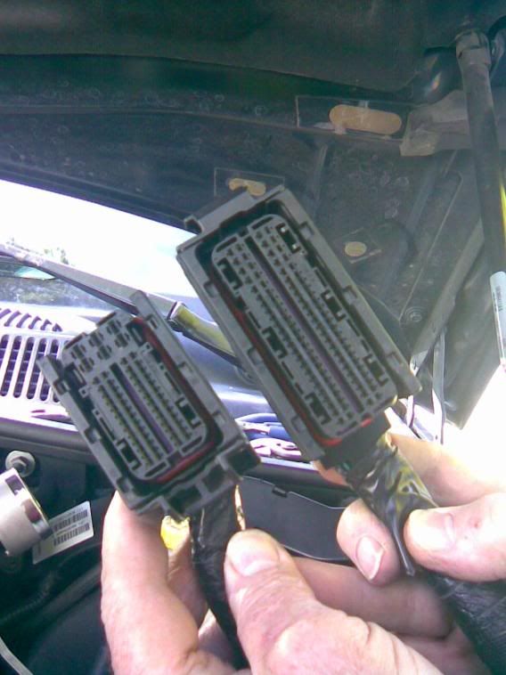
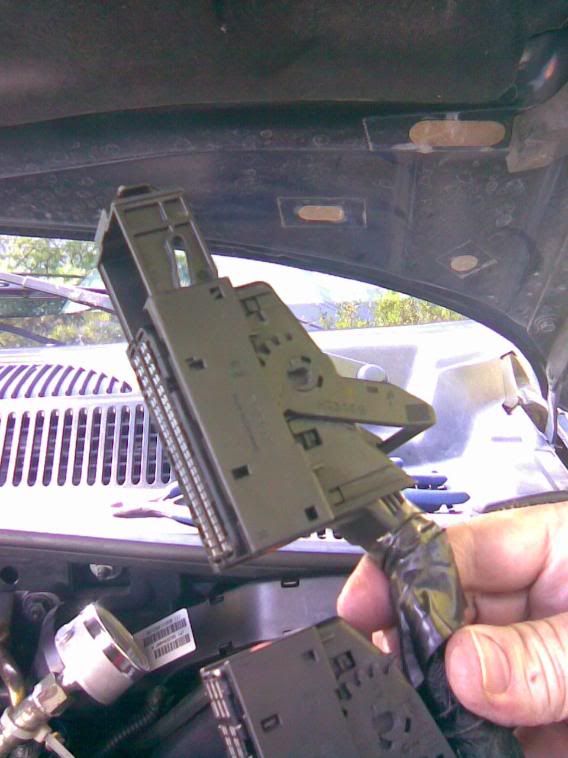
Here's C1 and C2 in proper position, latches closed
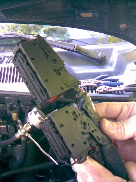
Same, latches open - push down on C1, remove, then pull up on C2
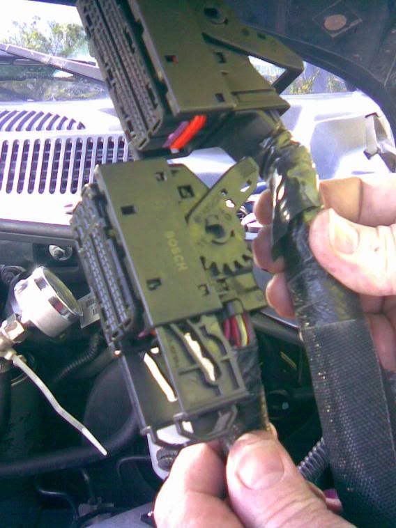
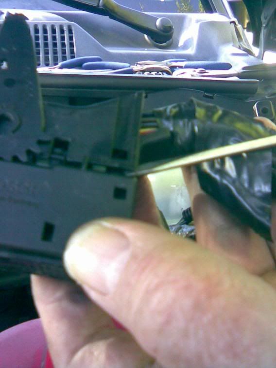
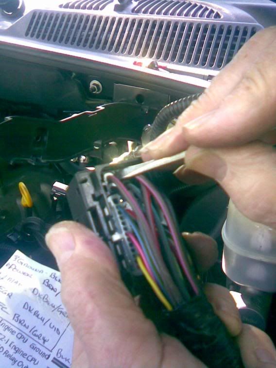
Using a small screwdriver to release the cover, two latches on C1, also on C2
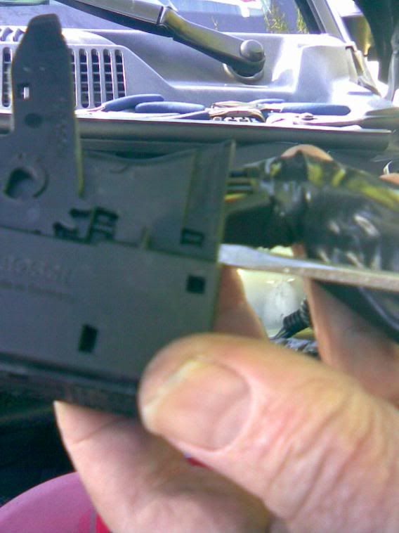
And, released
C2-58pin and C1-96pin, face-on
C1-68 AFC, Brn\Gry - SEGR 7 and 8
C1-85 MAF, DkBlu\Grn - SEGR 1 and 2
C1-90 EGR, DkBlu\Vio - SEGR 4 and 5
C2-1 +12v, DkBrn\Vio - SEGR 3
C2-2 Ground, Blk\DkGrn - SEGR 6
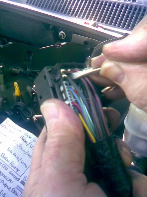
C2-17 T41, Yel\DkBlu - SEGR 9
Spliced - crimped, soldered, shrunk, good to go
When popping the covers back on, make sure the latch is fully extended and handle is at full travel - C1...............
And C2
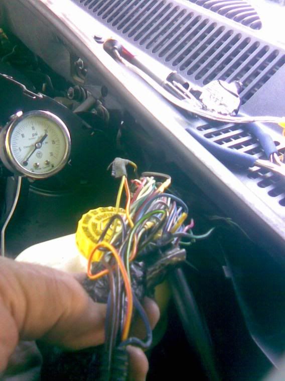
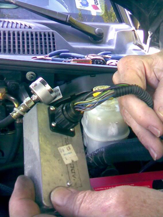
SEGR with factory wiring
Interestingly enuff, here is C1-11 Torque Management Request pin - hmmmm......what's gmctd up to, now, eh?
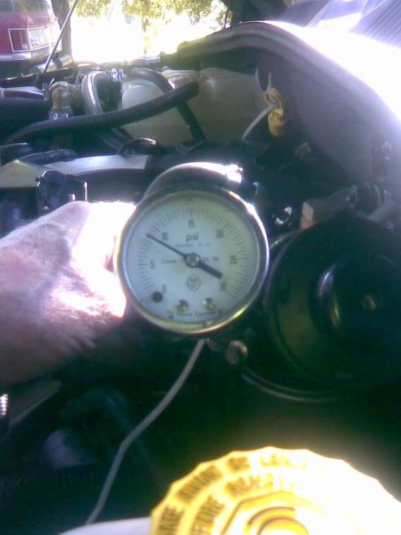
Equally as interesting, 8.5psi @ 55degF
A sealed rubber grommet thru the firewall is located just behind the fuel manager head, on the engine side - the SEGR harness may be fed thru that grommet to locate the module in the cabin, if so desired - see Bill Barq's post, somewhere above ^
http://picasaweb.google.com/bill.barg/J ... ingProject
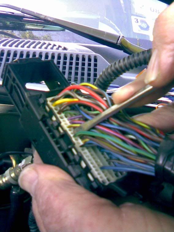
The splicing is easiest in the plastic harness tray on the firewall, but you'll still have to pull the ECM connectors to determine the correct wiring, as there are several of each color in that big harness
Unlatch and remove C1 - push the latch handle down, then pull the connector out, up and back to clear C2
Unlatch and remove C2 - pull the latch handle up, then pull the connector out and up from back of ECM
Carefully pull C1\C2 harness up and out to full extension from harness tray on firewall, clearing other wiring harnesses.
Pull the main harness tray off the firewall far as the brake booster, pop the cover off the tray using a small screwdriver on the latches
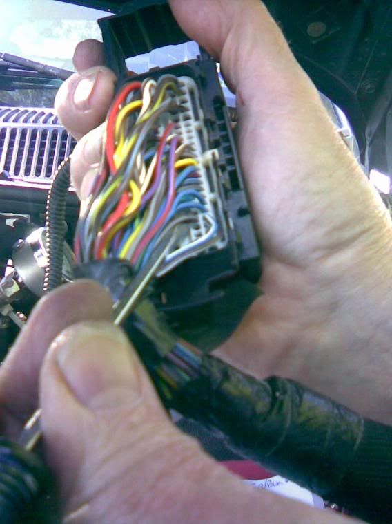
Un-tape and un-bundle the wires from the harness loom so you can separate and pull-trace the required wiring for splicing
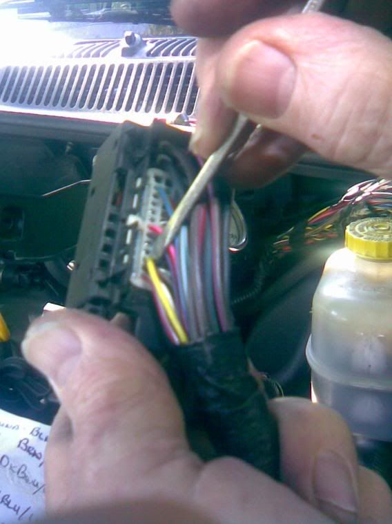
Locate the pins in the connectors, identifiable by the wire color
The pin numbers are visible on each connector face
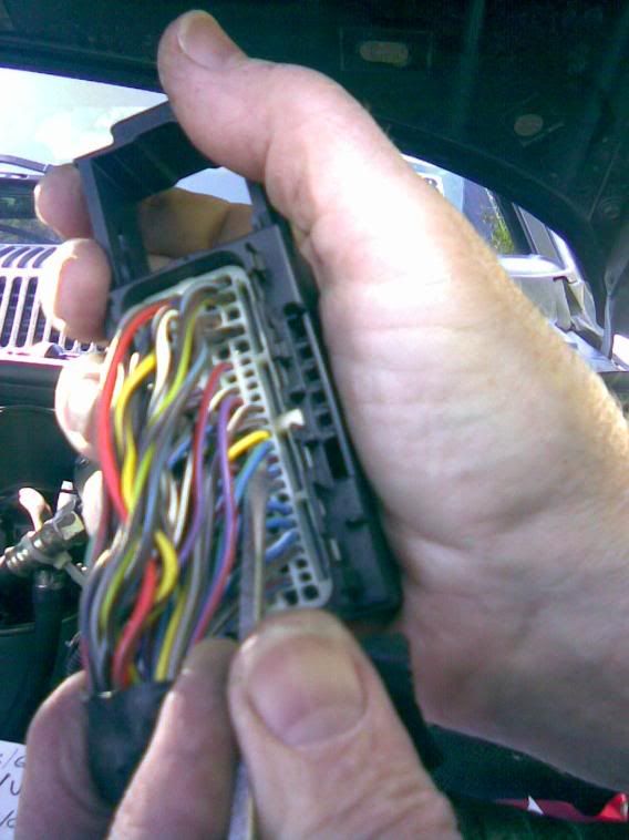
C1 is four columns of 24pins, counting top downward - 1-24, 25-48, 49-72, 73-96
C2 has 6 power pins across the top, 1-2, 3-4, 5-6
And four columns of 13pins counting top downward from the power pins - 7-19, 20-32, 33-45, 46-58
The male pins in the kit are for the box-mounted connector shell
The female pins are for the cable connector shell
Crimp is good - solder 'em if ya got 'em
The SEGR connectors are labled 1-2-3 in the top row, 4-5-6 in the second row, and 7-8-9 in the bottom row
Connector pin #'s correspond to termination points on the pcb:
Male box connector wiring from pcb
1=White - 1
2=Wh\Red str - 2
3=Red - 3
4=Blue - 4
5=empty, not used
6=Black - 6
7=Yellow - 7
8=Yel\Blk str - 8
9=Violet - 9
Female harness connector wiring
Cut the DkBlu\Grn MAF wire in two
1=Wh wire to Maf DkBlu\Grn
2=Wh\Red stripe to ECM MAF DkBlu\Grn
3=Red to C2-1 DkBrn\Vio +12v
Cut the DkBlu\Vio EGR wire in two
4=Blue to C1-90 ECM EGR DkBlu\Vio
5=Blu\Blk str to EGR solenoid DkBlu\Vio - used only with optional test jumper plug
6=Black to C2-2 Grnd Blk\DkGrn
Cut the Brn\Gry AFC wire in two
7=Yellow to ECM AFC Brn\Gry
8=Yel\Blk str to AFC valve Brn\Gry
9=Violet to C2-17 T41 Yel\DkBlu
Do 3,6,9 to C2 wiring first, as they are simple taps - the other 6 are cut and splice between C1 and the affected device
For 3,6,9, I carefully pushed a sharp awl thru the harness wire, tinned the bare SEGR wire, inserted it into the hole, soldered the joint and sealed it with black RTV, using a piece of tape for the curing mold.
The cut and splice joints were crimped, soldered and heat-shrinkable tubing used to insulate
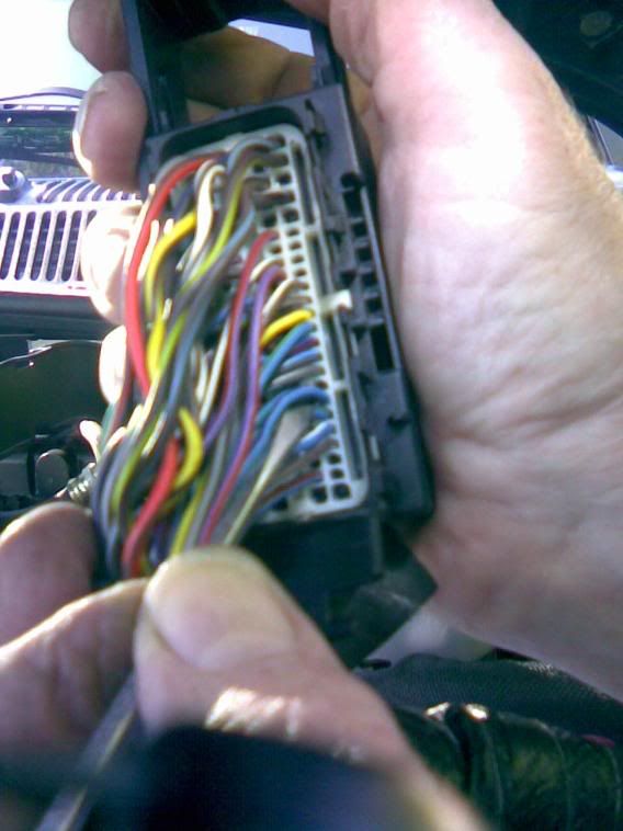
Locate each wire\pin at the connector, noting the color, then pull that wire away from the main harness, noting which wire moves in the main harness, trace it back to where you want to splice it - terminate both ends B4 proceeding to the next cut\splice
After each wire is cut\separated, the end toward the connectors is ECM, as ECM EGR or ECM AFC - the other end, toward the engine, is the device, as EGR or AFC
When reassembling the covers to the connectors, make sure the latch is fully extended and the handle is at max open travel
Tape everything back up, re-lay the harness in the tray such that all wiring beds-in and can be covered, pop the cover back on and onto the firewall studs
Position the ECM harness to connect C2 first by pushing C2 into position, keeping C1 harness back against the fender\firewall - push C2 squarely into it's nest, push the handle down - movement should be firm, but not difficult as connector seats
Now carefully feed C1 harness down in behind C2 harness - it'll fit, it was there when you started this gig - insert C1 into nest, pull the handle up as the connector seats
Connect 9-wire harness connector to the black box, crank it up, and yer good to go