LOST JEEPS
http://www.lostjeeps.com/forum/phpBB3/

192º Thermostat - Parts Diagram/dimensions added page 1
http://www.lostjeeps.com/forum/phpBB3/viewtopic.php?f=98&t=50940
Page 36 of 41

Author:  arengant [ Sat Mar 16, 2013 4:19 am ]
Post subject:  Re: 192º Thermostat - Parts Diagram/dimensions added page 1

Hey Mark,

Do you have an updated list in order of who's getting a wp from you?

Author:  ChesterCRD [ Sat Mar 16, 2013 5:23 pm ]
Post subject:  Re: 192º Thermostat - Parts Diagram/dimensions added page 1

arengant wrote:
Hey Mark,

Do you have an updated list in order of who's getting a wp from you?


I emailed Mark asking similar. He's working from (and updating) the list on page 1 of this thread.

Author:  papaindigo [ Mon Mar 18, 2013 4:48 pm ]
Post subject:  Re: 192º Thermostat - Parts Diagram/dimensions added page 1

Mark posted an update on his production status, # of units not people, here viewtopic.php?f=5&t=74131&start=60

Author:  kapalczynski [ Fri Mar 29, 2013 11:31 pm ]
Post subject:  Re: 192º Thermostat - Parts Diagram/dimensions added page 1

Update:

Mini Lathe I ordered came in a few days ago. I am very pleased with it. I tried it out to make the bypass insert and it is very accurate and easy to work with. I can now chuck on the inside of the piece with the small chuck and easily have room to machine the outside. It should be nice for working on the small stuff like the brass fittings as well.

It runs on any voltage from 100-240V and supplies voltage to a 90V DV motor thorough a adjustable speed control. So there won't be any heat issues with this one. No more having to switch belts to change speed either, its all adjustable with a knob! :D

It's literally less than 30lbs with chuck and everything.

I also just ordered 20 more thermostats so I should have enough of those for the 25ish cores i have as well.
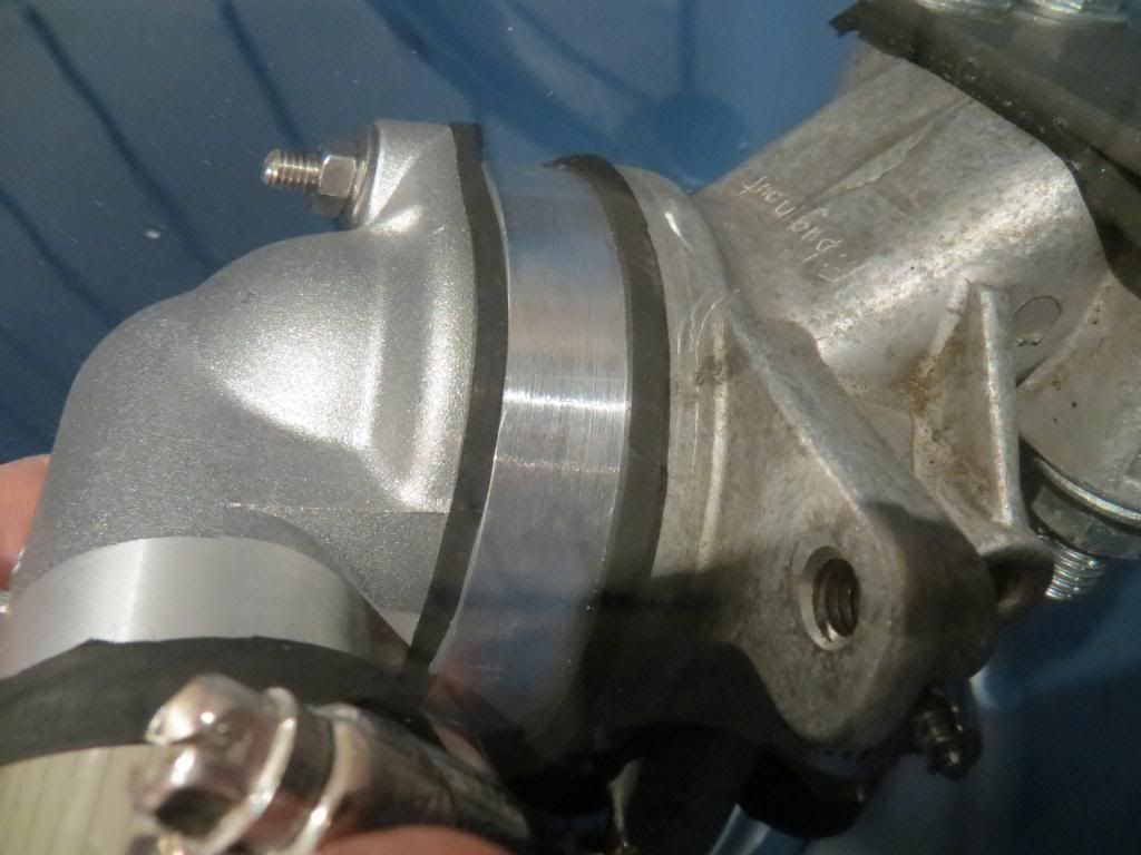
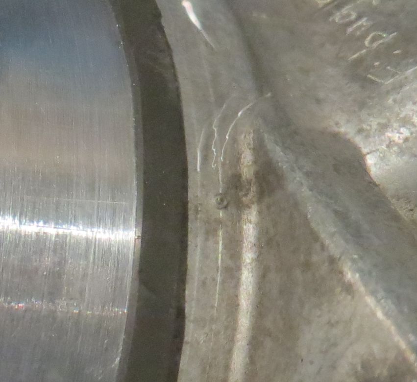
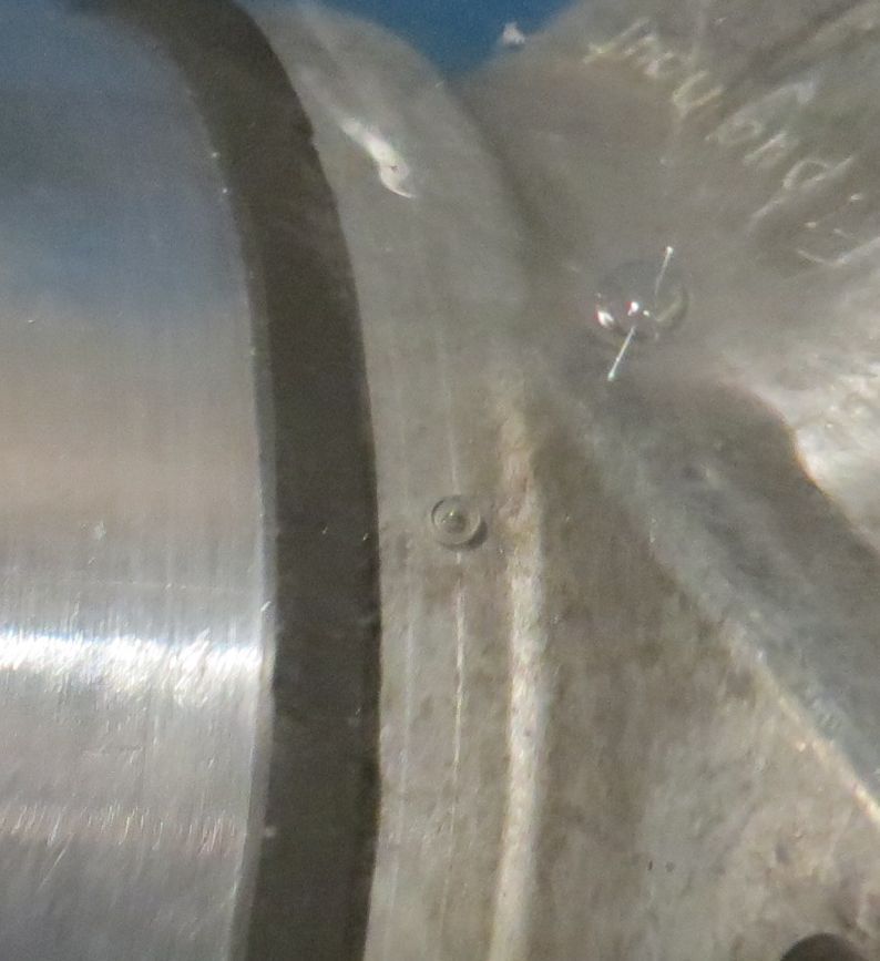
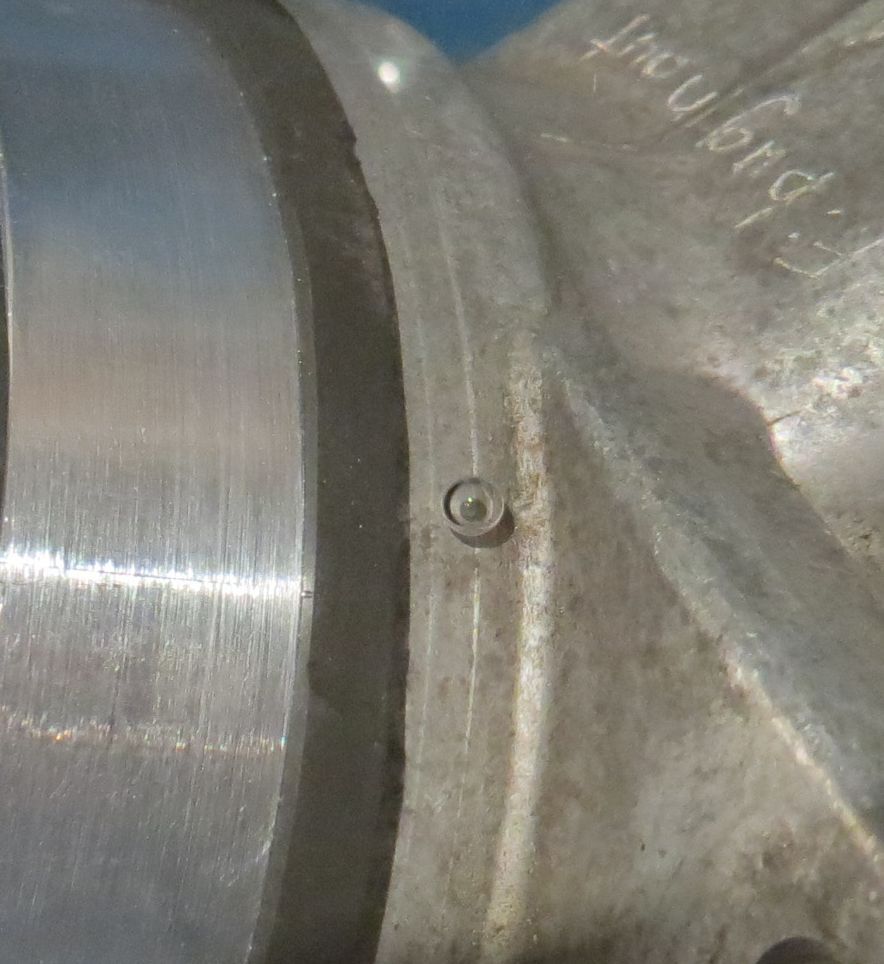
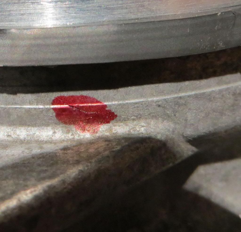
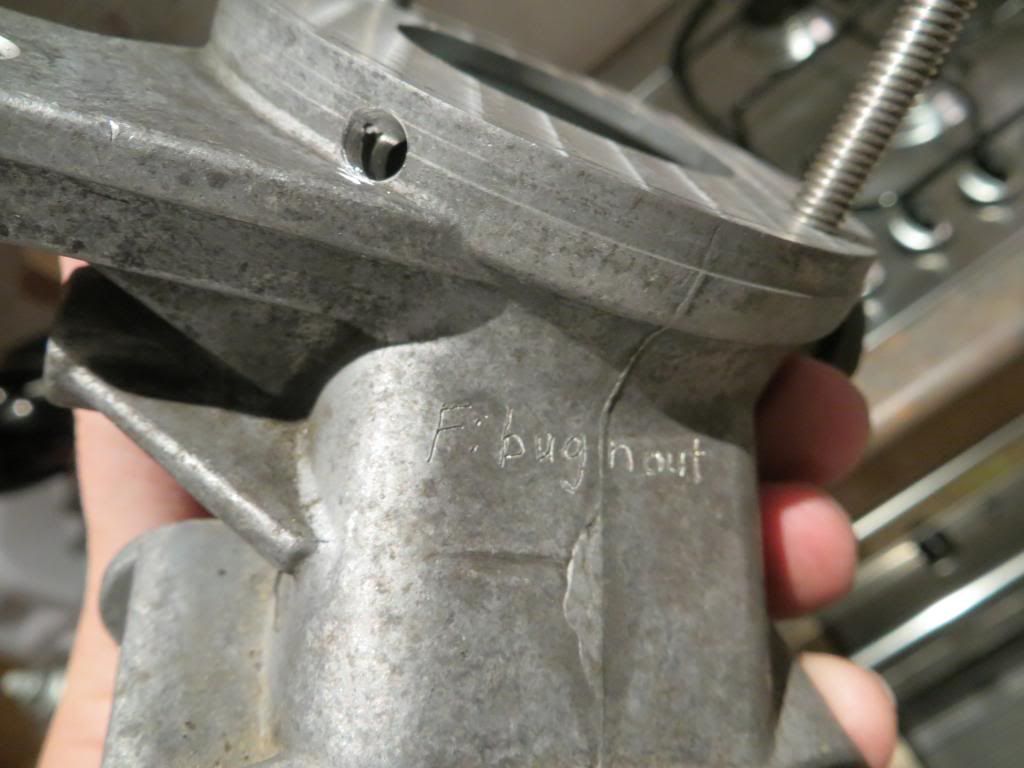
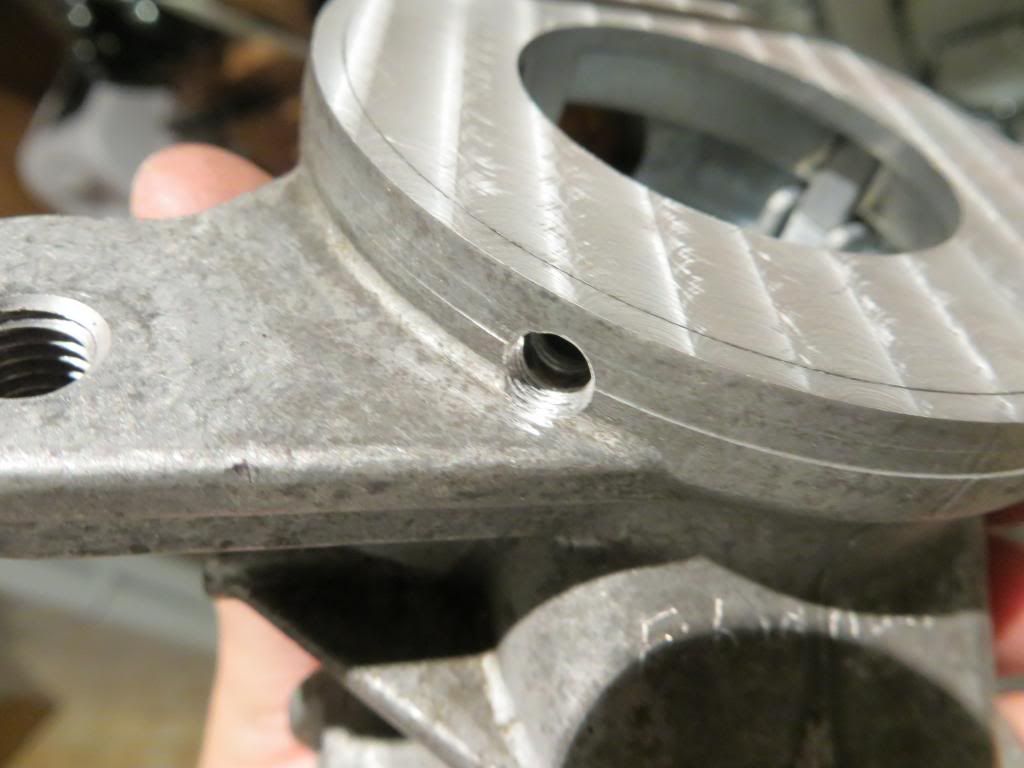
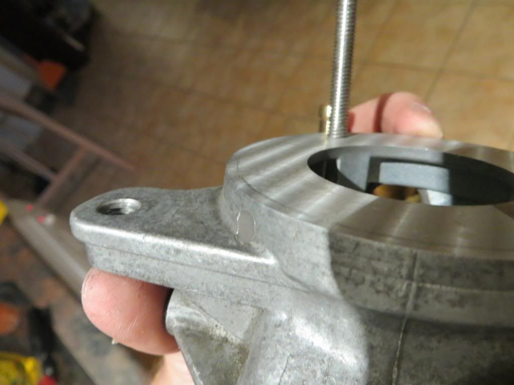
Bugnout,

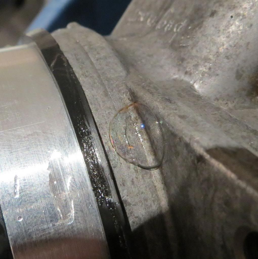
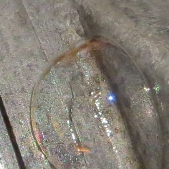
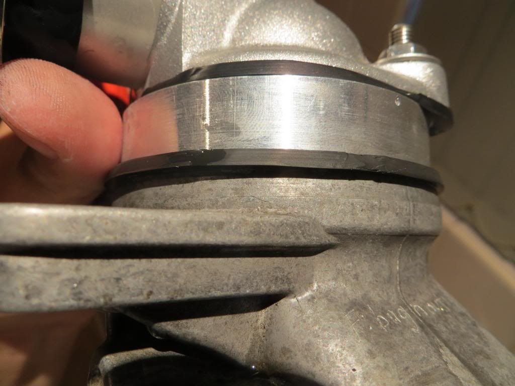
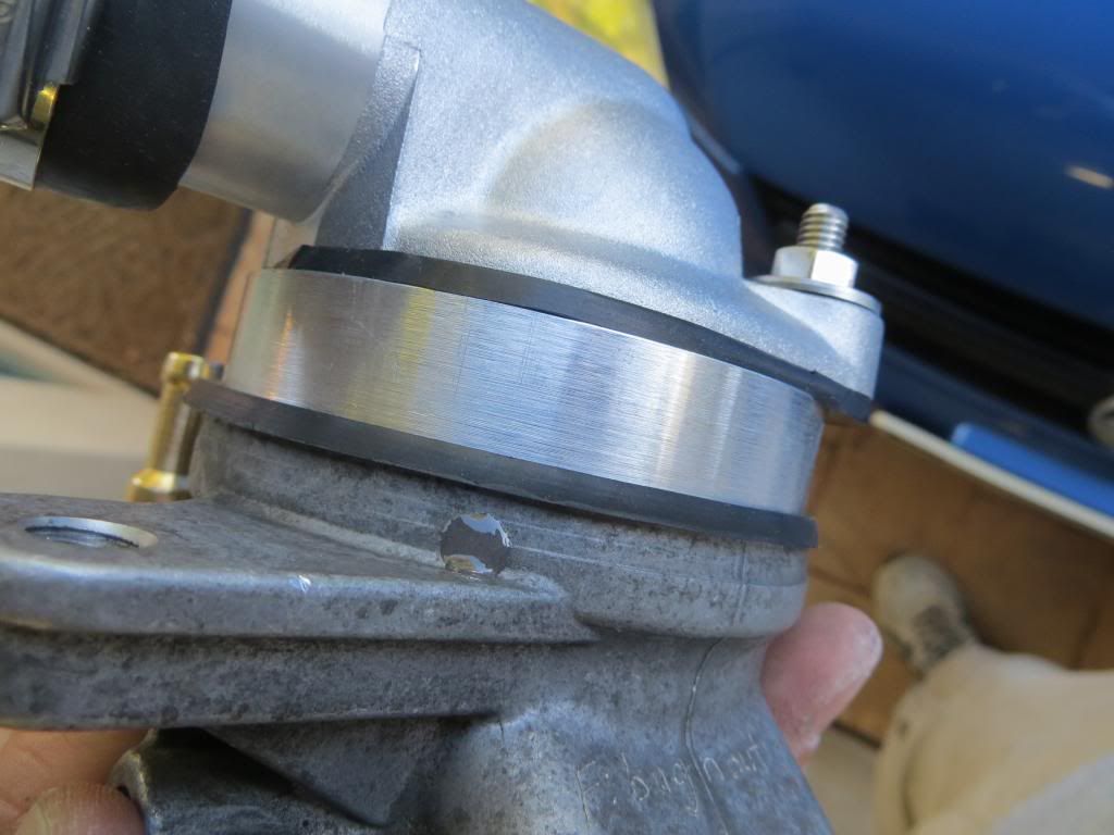
Your unit is machined flat, drilled/tapped, bypass insert is machined and pressed in, intermediate plate is machined/drilled, brass ports are machined. Next is removing the plastic ports, cleaning up the holes/threads and installing the brass. Then installing the studs and it should be about ready to pressure test.

- Mark

Author:  dgeist [ Sat Mar 30, 2013 2:43 pm ]
Post subject:  Re: 192º Thermostat - Parts Diagram/dimensions added page 1

Mark, what's the difference in time to add the brass fittings vs. leaving it with the default plastic (and do you have parts extras)? I know I'm next on the list and figure I should tell you if I want the brass :)

Also, is there any concern over galvanic corrosion between the brass and aluminum? I suppose as long as there's no electrolyte between the threads, its okay...

Dan

Author:  kapalczynski [ Sun Mar 31, 2013 1:41 am ]
Post subject:  Re: 192º Thermostat - Parts Diagram/dimensions added page 1

I don't believe corrosion to be an issue as the Antifreeze is formulated to have brass in the system seeing as it was already used in the previous thermostat housing in the thermostat and the factory temp sensor that screws into the housing is brass as well.

That being said, I cannot guarantee the brass is the same formulation and cannot guarantee no corrosion. It's your call if you want the plastic or the brass. I will tell you however the fittings are sealed/installed with JB Weld which is fairly inert to most chemicals and I highly doubt we will see any corrosion other than the traditional slight greening of the brass due to exposure of oxygen.

As far as lead time...I have 2 more sets of brass machined already so there won't be a difference for you. If everyone goes brass the lead time may compound a bit down the line though so others may get longer lead times.

In addition to that...the brass is fairly simple to machine and a pleasure to work with compared to aluminum. It chips and doesn't string while machining. It shouldn't hold things up much.

Author:  kapalczynski [ Sun Mar 31, 2013 1:44 am ]
Post subject:  Re: 192º Thermostat - Parts Diagram/dimensions added page 1

Another quick update.

Bugnout, your housing is just waiting for JB Weld to cure on the brass ports and the studs that I just installed. Another 24 hours or so and I should be good to assemble pressure test the unit.

- Mark

Author:  kapalczynski [ Mon Apr 01, 2013 5:31 am ]
Post subject:  Re: 192º Thermostat - Parts Diagram/dimensions added page 1

Aaaaand this is why I do a pressure test before I ship a unit out... :shock:

Bugnout,

I ran across an imperfection in your core during pressure testing. I'll post photo's below. There is actually a very VERY small crack in the housing itself near the roll crimp. I believe it to be a factory imperfection during casting. You can hardly see it with out the zoom on the camera even if you know where to look so it was never noticed.

Image

Image

Image

Image

Image

Image

Image

Image

Image

I'm not even sure if its enough for coolant to leak, but at 30 psi air was coming out so I went ahead and repaired the housing. I'm just waiting for that to cure at the moment and then another pressure test tomorrow.

Image

Image

Image

Image

To fix it, I drilled with a small drill bit and gradually went larger and larger until I was well beyond the crack. Then I tapped the hole to allow for some extra grip and filled it with JB Weld.

- Mark

Author:  kapalczynski [ Mon Apr 01, 2013 7:08 am ]
Post subject:  Re: 192º Thermostat - Parts Diagram/dimensions added page 1

Quick video of the leak pressurized at 30 PSI

http://www.youtube.com/watch?v=B9Chmq1-GcI&feature=youtu.be

It doesn't surprise me that much because I have ran across various pits in the aluminum while machining the units. I've had to take another thousandth or two off the deck height to get a smooth finish on some. I have also seen pits in the surface where the unit mounts to the block on one unit after scraping the gasket off. These I filled with JB weld as well. In both cases it looked like air bubbles were in the aluminum during the casting process.

Author:  papaindigo [ Mon Apr 01, 2013 8:28 am ]
Post subject:  Re: 192º Thermostat - Parts Diagram/dimensions added page 1

I've seen an essentially identical problem with aluminum tire rims. Pin hole flaw in OEM casting; fixed by a bit of sealant painted on the inside of the rim where the leak was. That fix held for the 75K miles I owned the vehicle.

Author:  bugnout [ Tue Apr 02, 2013 9:27 pm ]
Post subject:  Re: 192º Thermostat - Parts Diagram/dimensions added page 1

Excellent Mark. Can't wait to get it installed.

Love the Morissette, Isn't it ironic.... Not bad, but, may I recommend Joe Banamassa's "An Acoustic Evening at the Vienna Opera House" - Think you'll fine that its excellent music to work to.

Author:  kapalczynski [ Sun May 12, 2013 8:54 am ]
Post subject:  Re: 192º Thermostat - Parts Diagram/dimensions added page 1

ha ha, thx for the music tips. :P

Just an update,

Had my sister in town visiting us here in Australia the last several weeks so haven't had project time, hope to have time to get another finished soon.

- Mark

Author:  fastRob [ Sun May 12, 2013 3:27 pm ]
Post subject:  Re: 192º Thermostat - Parts Diagram/dimensions added page 1

Wow!
Still plugging away at this.....
I am impressed.

Author:  kapalczynski [ Fri Aug 23, 2013 7:02 am ]
Post subject:  Re: 192º Thermostat - Parts Diagram/dimensions added page 1

Found a bit of free time today...used it to start the next unit and get organized with the list/people, spare parts, etc. dgeist - worked on yours today a bit, update below.

This project exploded with people wanting a unit, not enough cores to start the program, and then I moved to Australia and lost all my free time so I have no hard feelings if anyone wants to bow out.

So if anyone wants their core back, though it would be a bit counter productive feeling for me seeing as I have machine time on all the units, i'm happy to send it. Keeping people waiting makes me feel even worse.

If you want to arrange a refund/core shipped back please contact me at awdv8@yahoo.com because my inbox on here is full of people/contacts in emails i can't delete for the tstat project.

My current list of cores I have (in order) from people that still need finishing - All these have the deck machined flat and the holes drilled:

dgeist - worked on this today, also has holes threaded with tap, insert machined and pressed in.
CATCRD
papaindigo
fastrob
crawdad-480
Buster
TJ2
Sir Sam
ColoCRD
ChesterCRD
castnblast
grywlfbg
AZ CRD
ATXKJ
DocB
Tim_Z
ColoCRDx2
GreenDieselEngineering
Mr Wolcott

Author:  CATCRD [ Sat Aug 24, 2013 12:35 am ]
Post subject:  Re: 192º Thermostat - Parts Diagram/dimensions added page 1

Woohoo! In moving up the list!

Author:  ColoCRDx2 [ Sat Aug 24, 2013 9:52 am ]
Post subject:  Re: 192º Thermostat - Parts Diagram/dimensions added page 1

Hey Mark -

I'm willing to wait, keep me on the list for sure!

You've missed a crazy year back here in Colorado, by the way. Mild winter, then we got hammered in April and early May. I think the number I've heard was 47" in April alone, maybe it was 37"... and now it seems that it's rained almost every day since late June.

Happy trails,
Doug

Author:  ChesterCRD [ Tue Aug 27, 2013 5:10 pm ]
Post subject:  192º Thermostat - Parts Diagram/dimensions added page 1

Thanks for the update! I really want to add a KapalStat to my sig one day. ;)

Author:  dgeist [ Tue Aug 27, 2013 5:21 pm ]
Post subject:  Re: 192º Thermostat - Parts Diagram/dimensions added page 1

Yep, I still want one. It'll probably go in at the same time as my new timing belt (at around 93k at the moment). Thanks for plugging away at this (no pun intended).

Dan

Sent from my subdural android implant using Tapatalk 2

Author:  audiboy86 [ Wed Aug 28, 2013 11:48 am ]
Post subject:  Re: 192º Thermostat - Parts Diagram/dimensions added page 1

kapalczynski - I didnt know you had gotten back into this I thought you were still in the land down under?

Author:  bugnout [ Mon Nov 25, 2013 10:24 am ]
Post subject:  Re: 192º Thermostat - Parts Diagram/dimensions added page 1

Hey Mark, Finnaly got the new thermostat installed as part of the work to replace the head gasket, and it works great. Now that its below freezing here, the cabin is nice and toasty and the temp gauge is rock solid. Sure want to thank you for the high quality of your work. I'll post a picture when I get a chance.

Thanks Again.

Page 36 of 41 All times are UTC - 5 hours [ DST ]
Powered by phpBB © 2000, 2002, 2005, 2007 phpBB Group
http://www.phpbb.com/