It is currently Fri Apr 26, 2024 1:51 pm

All times are UTC - 5 hours [ DST ]


Post new topic Reply to topic  [ 21 posts ]  Go to page 1, 2  Next
Author Message
 Post subject: Oil Pressure Gauge How-To *pics*
PostPosted: Fri Mar 23, 2012 11:32 pm 
Offline
LOST Addict
User avatar

Joined: Thu Sep 06, 2007 9:51 pm
Posts: 6297
Location: Somewhere between Heaven and Hell... But it is really hot here on Earth...
Well, it is finally installed!

The first of two oil pressure gauges is installed in my CRD now, with the second one going onto Papaindigo's CRD tomorrow as part of the turbo install.

A couple quick observations of what you can expect from this install: NO DRILLING / TAPPING! Yes, that is correct, it has a threaded plug that you will need to extract, then you can use that port and just put it all together. The front port that I was hoping to use... Completely useless. You can see it, but there isn't really any way to get TO it without removing a LOT and most likely draining the cooling system. You will need an adapter to change the metric threads to 1/8" NPT, but after that, it is just a matter of installation.

What do you need to remove to install this in the furthest-back port? Surprisingly little.

Start off by removing the airbox and the two air hoses on the turbo, you will need the room. If you feel adventurous and have a long support, you might also want to remove the passenger-side hood strut. Slip some needle-nose pliers under the metal band on each end of the strut and gently pull out. It should lock in the open position, then just slide it off the bulb. Again - you will need the room, this is a long reach.

Unbolt the two support nuts on the coolant tank, and flip it upward toward the passenger fender. The goal is to never drain the cooling system, and I have managed to do all this with the bottle still attached and full. Hopefully your hoses will allow you to do the same. If you can, after removing the turbo's heat shield, you may want to move the water bottle over the top of the turbo and forward. Everything else you do will be behind the turbo, from the fender side, and it is really in the way there. The smaller hose on the passenger side of the bottle was the only one I needed to unhook (on another day) and re-route around the AC lines so the bottle can be more easily moved toward the front.

OK - Pull the turbo's top heat shield if you haven't already.
Unlock the clamp on the turbo downpipe, and let the pipe droop toward the fender and down as much as possible - you need it out of the way.
Reach down to the next heat shield, this one may or may not have a bolt into the bell housing, and it should have one pointing away from you just out of sight under the exhaust manifold. 10mm socket will pull that out, remove the heat shield.

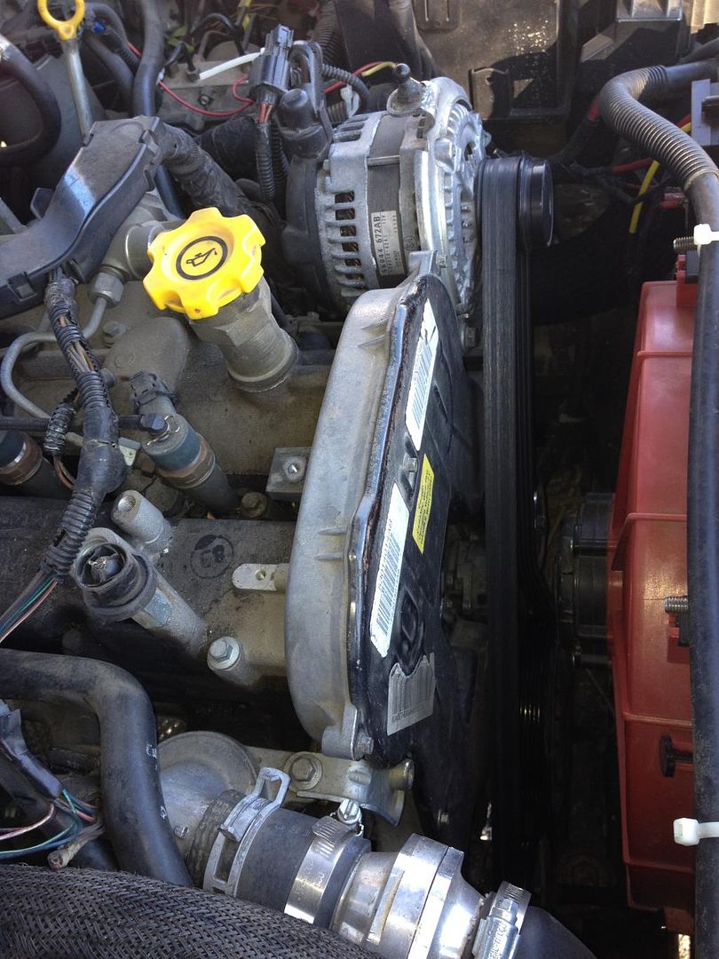
Now your target is in sight!

Image

This is a plug with a copper washer under it, and REALLY cranked tight. It is a 6mm hex, I would strongly suggest using a 3/8" socket-adapter hex to remove it. I got a metric kit at Home Depot for $12 with this size in it, worked great. Take the socket adapter and put it in WITHOUT any extensions on it, and using a 1/4" extension into the top of the socket (yes I know it will be too small) tap it HARD with a wrench or hammer - The hex on mine *felt* like it was correctly seated... And I nearly messed up the socket because it had gotten stuck on filth only about 1/8" in or so. Make sure that thing is IN THERE before you try to unlock it.

You WILL need a wobble head extension rod to get at it, and I would suggest at least 2 full 1-foot extensions to get the wrench out to the hood line so you have the leverage you will need. You may also need to do what I did, extending your socket handle using a cheater bar or large box wrench to get enough force. Once it cracks loose however, it should come right out without fuss.

Now, you have this image in front of you!

Image
Image

Set your self up with the adapter, and then some of the following parts:
Image
Image

Note the plug in those two images, you can discard that now.

Image
Image

These parts might be available at your local NAPA, but I also found them at Home Depot. This is basic brass 1/8" NPT stuff.

Here it is installed:

Image

Now, the problem you may encounter if you are using the same adapter design we are - That hex on the base is 19mm or 3/4"... And is ***VERY*** close to the bell housing. So close that even a thin-wall socket will barely fit. I managed to get that adapter tight to the copper washer with a socket I had, but just barely. The problem is there is a protrusion on the bell housing that sticks right where you need the socket to be. Future versions of this adapter will hopefully address this by being milled smaller to an 18mm or 17mm socket size. You CANNOT tighten the brass and expect it to tighten the adapter onto the crush washer. I tried, and wasn't happy with the results, it wasn't tight enough.

Once the adapter is in, install the brass extension and the elbow you have chosen for your sensor. I used the 90 degree elbow, and this is what the final setup looks like:

Image

I was not able to re-install my heat shield on this, because that sensor is so freakishly huge. Papaindigo's sensor is smaller, so we might be able to modify the shield and use it on his, but I'm not convinced of that yet. I realize that there is a lot of heat potential in that area, but at the same time... There isn't anything hazardous that will happen if the shield isn't there - The worst that will happen is that the sensor quits working. I'm not expecting that however. I had removed my forward heat shield which is a LOT closer to the thermostat housing several weeks ago, and nothing has happened there yet. Yes, I'm putting that forward shield back in tomorrow when I go for another look at this to check for leaking. Everything here has at least 2 inches of clearance to a heat source, so I think the setup will be fine. The hottest points are on the turbo anyway, which is further away.

Operating pressures - I would like to get a baseline recorded from anyone that does this, so people can confirm if their system is working normally. I have a fresh oil change, and with a warm engine, it is running about 35psi at 60mph, 40psi at 70mph, with idle at 20psi. Remember, this is measuring the pressure gallery that feeds the 4 cylinders and the turbo, so there are a lot of outlets for the pressure. I would like the numbers to be higher, but I think this is about right. I will be contacting VM on Monday for their opinion about these pressures... But at the same time, my CRD is running great, so these numbers must be correct.

_________________
Proud supporting vendor of LOST Jeeps
TRAVELING CRD TECH. I come to you!
Need help? Just ask! I've taken it apart more than most.
Email jeep [at] maincomputer [dot] com - BOARD MESSAGING IS BROKEN
Over 125 CRDs currently driving with my timing belt, rockers, or ARP Studs.
Bad noises = REALLY bad things.


Top
 Profile  
 
 Post subject: Re: Oil Pressure Gauge How-To *pics*
PostPosted: Mon Mar 26, 2012 11:20 am 
Offline
LOST Member
User avatar

Joined: Thu Sep 11, 2008 2:13 pm
Posts: 466
Location: Tupelo, MS
This should be a sticky in the the tech section........great write up!!! Any pics of your gauge install showing the pressures you're running???

_________________
2005 Black CRD KJ____Full GDE turbo kit, EHM, 6.5L GMCTD lift pump, euro tq conv, 31" Duratracs on 15x7 Procomps w/3.75"bs
2.5" lift, full skids, Super Skink Sliders, front JBA Steel Diff w/True-Trac___Powertax "No-Slip" locker rear
Tow Rig: 2003 Silver 2wd Dodge 2500 reg. cab 5.9 Cummins (highly modded with 550hp/1200tq+)


Top
 Profile  
 
 Post subject: Re: Oil Pressure Gauge How-To *pics*
PostPosted: Mon Mar 26, 2012 9:12 pm 
Offline
LOST Addict

Joined: Thu Oct 20, 2005 5:42 am
Posts: 2111
Location: Fort Collins, CO
Looks like a good location to measure oil pressure. I just worry about one thing. What you have with that sensor setup is kind of a heavy weight on the end of a brass tube, bolted directly to the engine block. With the vibration of the diesel engine, that system is going to be flexing and vibrating like a tuning fork. Brass isn't exactly known for its fatigue strength, and I worry if that sensor is heavy enough, something is going to crack and dump your oil in a hurry. I would investigate a shorter, stouter setup with a smaller sensor that can screw directly in with no extension. I'm not trying to take anything away from your project - it's a good idea. I'm just going off what I've seen on our "shaker table" at work for vibe testing parts, and seeing steel studs snap off after a few days only holding a modest weight out on the end of them.

Also wanted to add, those pressures you're seeing are within about 2psi of what I see with my sensor at the filter. (5W-40 oil, engine at full temp)

_________________
05CRD: GDE Hot ECU & TCM tunes, Provent, Cat filter, Facet lift pump, TransGo kit, Florida TC, Samcos, stainless brake lines, HDS thermostat, Renegade light bar,
RL super sliders, Bilstein adjustables, Al's Gen 4.5 Arms, 235/85-16 Duratracs, DTT rear, Elocker front, EVIC+TPMS, Turbo timer, McNally pillar gauges, Weeks Stage II kit.


Top
 Profile  
 
 Post subject: Re: Oil Pressure Gauge How-To *pics*
PostPosted: Mon Mar 26, 2012 10:30 pm 
Offline
LOST Junkie

Joined: Mon Mar 24, 2008 10:26 pm
Posts: 943
Location: West Coast, Canada
CATCRD wrote:
Looks like a good location to measure oil pressure. I just worry about one thing. What you have with that sensor setup is kind of a heavy weight on the end of a brass tube, bolted directly to the engine block. With the vibration of the diesel engine, that system is going to be flexing and vibrating like a tuning fork. Brass isn't exactly known for its fatigue strength, and I worry if that sensor is heavy enough, something is going to crack and dump your oil in a hurry. I would investigate a shorter, stouter setup with a smaller sensor that can screw directly in with no extension. I'm not trying to take anything away from your project - it's a good idea. I'm just going off what I've seen on our "shaker table" at work for vibe testing parts, and seeing steel studs snap off after a few days only holding a modest weight out on the end of them.


Do you think 316 Stainless would withstand the vibration? Judging from the pictures, although hard to tell, it appears space constraints are limiting the configuration. He may have a hard time finding a more compact sending unit, but I know you can get the adaptors...just going to have to pay for them.

_________________
2006 Liberty CRD Limited

Provent @ 43,000 km
SEGR in progress
SAMCO Sport hoses @ 48500 km
Goodyear Wrangler Duratrac LT225/75R16


Top
 Profile  
 
 Post subject: Re: Oil Pressure Gauge How-To *pics*
PostPosted: Mon Mar 26, 2012 11:18 pm 
Offline
LOST Addict
User avatar

Joined: Thu Sep 06, 2007 9:51 pm
Posts: 6297
Location: Somewhere between Heaven and Hell... But it is really hot here on Earth...
Adaptors were problem #2, MASSIVE space limitations being problem #1. You have no idea how cramped that spot is, not the least of which is the flipping bellhousing that has a molding sticking right out toward where you need to be able to put a socket, and the engine block effectively cramping your style the other way. Open end wrenches are just right out, forget about using one to put that adapter in the hole. Open wrenches have to be used for tightening the square brass elbow or sensor... But there is space for both those uses, once you get away from the block and bellhousing. Still, it is cramped in there.

Now... On the second CRD we installed this mod on this weekend (Papaindigo's) we had learned a bit about the job, and since I posted this write-up after doing mine, it didn't get in there. I'm planning to update the thread a little, but at the same time, this is heavily dependent on what adapter you have to work with. As I have an angle grinder to work with during this job, we decided to take a gamble and try to take a single MM off the hex of our adapter. With some careful grinding, it worked perfectly and I was able to get an 18mm socket into that EXTREMELY tight place and put some meaty torque to it. On mine, I was just barely able to grab the top of the hex points with a thin-wall 19mm... So doing the adapter to 18mm is a much better option. I was also able to get the lower heat shield back in place by only using the bellhousing bolt hole, and I think that should do a fair job of protecting the sensor from too much excessive heat. Time will determine.

CatCRD - I can appreciate your fears, but at the same time - This is on a 1.5 inch nipple, and cranked down deeply, so I would suspect in actuality about 1 inch exposed from the bottom adapter. I'm not terribly worried about vibrations in such a short moment arm, especially since the brass tube itself is decently thick, but I will attempt to keep an eye on it. Papaindigo's sensor probe is smaller, so that might help in his case if there is such an issue.

Getting back in there on a stock engine is actually not terrible, just pull the water bottle out of the way and the upper heat shield, then drop the exhaust pipe. Working in there with a turbo in place isn't the most fun, but it is possible. Perhaps I could find another smaller sensor that is compatible and go with that one. As for the pressure readings... It is interesting that they would be so similar, but I'm much more concerned with detecting a sudden pressure drop from a turbo failure. I don't think that I would get a good enough reading from the output of the oil pump, compared to reading close to the source of potential leaks.

_________________
Proud supporting vendor of LOST Jeeps
TRAVELING CRD TECH. I come to you!
Need help? Just ask! I've taken it apart more than most.
Email jeep [at] maincomputer [dot] com - BOARD MESSAGING IS BROKEN
Over 125 CRDs currently driving with my timing belt, rockers, or ARP Studs.
Bad noises = REALLY bad things.


Top
 Profile  
 
 Post subject: Re: Oil Pressure Gauge How-To *pics*
PostPosted: Tue Mar 27, 2012 1:05 am 
Offline
LOST Newbie
User avatar

Joined: Sun Sep 04, 2011 9:56 pm
Posts: 66
i too installed a glowshift oil pressure gauge but i installed my sensor on a T behind the oil filter. my readings at 60 and 70 are basically the same give or take a few psi, but at idle im only seeing about 12 psi!! :( any thoughts?

_________________
06 cummins 3500 many mods 600+hp


Top
 Profile  
 
 Post subject: Re: Oil Pressure Gauge How-To *pics*
PostPosted: Tue Mar 27, 2012 9:41 am 
Offline
Lifetime Member
Lifetime Member
User avatar

Joined: Wed Mar 08, 2006 6:15 pm
Posts: 2733
Location: Atlanta GA
Knowing that it's probably not the best gauge around but that it WOULD fit the factory harness, is there any chance of compatibility with the factory oil gauge? What does it have for threading and I couldn't find reference to the threading of the adapter pictured above...is that a stock item somewhere or did you have to have it machined?

Dan

_________________
Image
2005 Silver CRD Limited :JEEPIN:
245/75R16 GoodYear Duratracs
Fumoto drain | ProVent CCV Filter
Stanadyne FM100 filter | Cummins fuel pump
GDE Eco | SEGR | BoulderBars | FrankenLift | Frankenskids


Top
 Profile  
 
 Post subject: Re: Oil Pressure Gauge How-To *pics*
PostPosted: Tue Mar 27, 2012 11:54 am 
Offline
LOST Addict
User avatar

Joined: Thu Sep 06, 2007 9:51 pm
Posts: 6297
Location: Somewhere between Heaven and Hell... But it is really hot here on Earth...
We don't have a factory oil gauge, we have a factory "idiot light" which is most likely an "on below 5 psi" type. The problem is... If you are only getting 5psi at the filter / oil pump outlet, you have already lost all your oil AND your engine has probably told you it is dying by making bad sounds. I don't know what to say about only reading 12psi at idle... At least you are reading something? *shrug* The information we are gathering here is important because if there are any solutions to be offered... Now we have the knowledge to know we NEED a solution, whether that comes from us or from VM. I know I'm not crazy about such a low pressure... But I also don't know what to do about it. I don't think there is an upgraded oil pump available for our engine is there? More than that... Tearing the engine apart to get to it would be an evil job. If there was such a thing as an external oil pump, I do know where it could be mounted easily - right on the front of the oil pan. The passenger side of the oil pan has a hex plug in it that leads directly into the pressure system, I would have to take another look to see if that feeds from or to the filter. I think it is part of the outlet of the oil filter.

The adapter was machined from the existing Chrysler oil gallery fitting that is designed to feed the turbo. Papaindigo and I were both amazed that Mopar even stocked that fitting, much less had 3 of them available for him to purchase and modify. In the course of a normal CRD's life, you wouldn't ever need to replace that part.

If I remember correctly, the size of that hole is M14x1.5 or M14x1.25... We could have adapters made from a standard bolt, but they would also need to machine the head down to 18mm for clearance with a socket. You still have the clearance issue with the bellhousing right there, so even with the smaller probe that Papaindigo's gauge came with, I don't think it would have threaded in neatly without hitting something.

As far as the vibration concerns, I thought about that a little more and this is what I came up with - The longer a moment arm or the heavier the object at the end, the more damage can be caused by vibration oscillations. In this case, everything would be moving in the same directions because it is all connected, and the ultimate intensity of the vibration is small because the engine doesn't rock back and forth more than a 1/8" or so when viewed from the top - very far from its own fulcrum of the mounts. This sensor is mounted very close to the engine mount, which should minimize the vibration potential energy that can be imparted.

_________________
Proud supporting vendor of LOST Jeeps
TRAVELING CRD TECH. I come to you!
Need help? Just ask! I've taken it apart more than most.
Email jeep [at] maincomputer [dot] com - BOARD MESSAGING IS BROKEN
Over 125 CRDs currently driving with my timing belt, rockers, or ARP Studs.
Bad noises = REALLY bad things.


Top
 Profile  
 
 Post subject: Re: Oil Pressure Gauge How-To *pics*
PostPosted: Wed Mar 28, 2012 12:14 pm 
Offline
LOST Junkie
User avatar

Joined: Sat Dec 20, 2008 7:02 pm
Posts: 607
props for figuring this crazy problem out! I defiantly want to get a gauge in mine, if you have time it would be nice to see an itemized list of things required for the install. I guess I could read through the post but I would be worried I will miss something and then tare into the install and not have what I need.
Nice pics !

_________________
-05 Dark Khaki Limited CRD. GDE ECO tune. In-tank lift pump, Transgo doo doo kit, B&M trans cooler, replaced trans solenoid pack and filters, Newer Michelin tires, Timing belt with all related parts replaced at 110,000miles.


Top
 Profile  
 
 Post subject: Re: Oil Pressure Gauge How-To *pics*
PostPosted: Wed Mar 28, 2012 12:18 pm 
Offline
LOST Junkie
User avatar

Joined: Sat Dec 20, 2008 7:02 pm
Posts: 607
Also, I don't have much experience with oil press gauge installs but would you think a mechanical sending unit would be smaller and more suited for the location?

_________________
-05 Dark Khaki Limited CRD. GDE ECO tune. In-tank lift pump, Transgo doo doo kit, B&M trans cooler, replaced trans solenoid pack and filters, Newer Michelin tires, Timing belt with all related parts replaced at 110,000miles.


Top
 Profile  
 
 Post subject: Re: Oil Pressure Gauge How-To *pics*
PostPosted: Wed Mar 28, 2012 1:44 pm 
Offline
Lifetime Member
Lifetime Member

Joined: Sun Mar 28, 2010 9:15 am
Posts: 5431
Location: Tallahassee, Florida
The "adapter" was fabricated by drilling and tapping to 1/8NPT a turbo oil line feed fitting part 5066814-AA ($7.50). We also used the associated washer 24030016 ($1.85) but that can be avoided by simply reusing the washer that's on the plug you remove.

The "adapter" can also be fabricated out of a standard 14mmX 1.5 bolt cut to just short of 1/2" in length and drilled thru and tapped for 1/8NPT.

EDIT - behind the bracket on which the fuel filter head is mounted is a rubber grommet the other side of which is above the go pedal on the inside. I suspect it's leftover from when there was a throttle cable. Use this for routing wiring into the cab. BUT don't try to remove and reinstall the grommet; just cut an "X" in it with a skill knife and route the cable. If water worries you seal with silicone.

_________________
Sold to LOST member my 05 Ltd, GDE Stg II turbo + TCM tune, SunCoast TC w. Transgo kit, Steiger window regulators, Samcos, Fumoto valve, 2nd gen filter head with Lub. Spec. bleeder, Hayden clutch & 11 blade fan, inverted spare, P-1 battery, BF Goodrich Long Trail TAs, Etecno1 glow plugs, timing belt at 50K miles/8 yrs


Last edited by papaindigo on Thu Jun 06, 2013 6:41 am, edited 1 time in total.

Top
 Profile  
 
 Post subject: Re: Oil Pressure Gauge How-To *pics*
PostPosted: Tue Dec 18, 2012 3:43 pm 
Offline
LOST Junkie

Joined: Sun Dec 18, 2011 1:15 pm
Posts: 776
Location: Eastern US
Bump.

_________________
Grid power- the one true essential

2005 Liberty CRD- ARP studs, Fumoto, Hayden FC, inline Tstat, ETechno 7v GP, Platinum P1, in-tank lift pump.
1983 Volvo D24T
1981 Volvo D24
Dodge Cummins TD
Case 580B
Mitsubishi MT180 diesel
Kubota BX25 diesel


Top
 Profile  
 
 Post subject: Re: Oil Pressure Gauge How-To *pics*
PostPosted: Tue Dec 18, 2012 11:54 pm 
Offline
LOST Junkie

Joined: Sun May 21, 2006 5:28 pm
Posts: 605
Location: Michigan
Just FYI, the sensor on the KJ is an actual sensor not an "idiot light" that opens as 0.5bar.
If you have a decent type of scan tool, you should be able to read the oil pressure that's broadcast on the bus.

geordi wrote:
We don't have a factory oil gauge, we have a factory "idiot light" which is most likely an "on below 5 psi" type. The problem is... If you are only getting 5psi at the filter / oil pump outlet, you have already lost all your oil AND your engine has probably told you it is dying by making bad sounds. I don't know what to say about only reading 12psi at idle... At least you are reading something? *shrug* The information we are gathering here is important because if there are any solutions to be offered... Now we have the knowledge to know we NEED a solution, whether that comes from us or from VM. I know I'm not crazy about such a low pressure... But I also don't know what to do about it. I don't think there is an upgraded oil pump available for our engine is there? More than that... Tearing the engine apart to get to it would be an evil job. If there was such a thing as an external oil pump, I do know where it could be mounted easily - right on the front of the oil pan. The passenger side of the oil pan has a hex plug in it that leads directly into the pressure system, I would have to take another look to see if that feeds from or to the filter. I think it is part of the outlet of the oil filter.

The adapter was machined from the existing Chrysler oil gallery fitting that is designed to feed the turbo. Papaindigo and I were both amazed that Mopar even stocked that fitting, much less had 3 of them available for him to purchase and modify. In the course of a normal CRD's life, you wouldn't ever need to replace that part.

If I remember correctly, the size of that hole is M14x1.5 or M14x1.25... We could have adapters made from a standard bolt, but they would also need to machine the head down to 18mm for clearance with a socket. You still have the clearance issue with the bellhousing right there, so even with the smaller probe that Papaindigo's gauge came with, I don't think it would have threaded in neatly without hitting something.

As far as the vibration concerns, I thought about that a little more and this is what I came up with - The longer a moment arm or the heavier the object at the end, the more damage can be caused by vibration oscillations. In this case, everything would be moving in the same directions because it is all connected, and the ultimate intensity of the vibration is small because the engine doesn't rock back and forth more than a 1/8" or so when viewed from the top - very far from its own fulcrum of the mounts. This sensor is mounted very close to the engine mount, which should minimize the vibration potential energy that can be imparted.


Top
 Profile  
 
 Post subject: Re: Oil Pressure Gauge How-To *pics*
PostPosted: Mon Apr 01, 2013 4:16 pm 
Offline
Lifetime Member
Lifetime Member

Joined: Sun Mar 28, 2010 9:15 am
Posts: 5431
Location: Tallahassee, Florida
UPDATE - R2.0 found that McMaster-Carr has a M14-1/4NPT adapter for about $7 (PN 4936K155). It probably will work but may require a bit of grinding as geordi and I found clearance in there is really tight. Shaving a bit off the head with a disc sander/cutoff blade to turn the 0.75"/19mm hex head into the next size down made things a lot easier on my install. For what it's worth McMaster-Carr has as stainless steel thick wall 1.5" nipple PN 46755K22 and a stainless steel elbow PN 46755K22 for about $5@ if the use of brass plumbing hardware worries you.

_________________
Sold to LOST member my 05 Ltd, GDE Stg II turbo + TCM tune, SunCoast TC w. Transgo kit, Steiger window regulators, Samcos, Fumoto valve, 2nd gen filter head with Lub. Spec. bleeder, Hayden clutch & 11 blade fan, inverted spare, P-1 battery, BF Goodrich Long Trail TAs, Etecno1 glow plugs, timing belt at 50K miles/8 yrs


Top
 Profile  
 
 Post subject: Re: Oil Pressure Gauge How-To *pics*
PostPosted: Tue Apr 02, 2013 11:07 pm 
Offline
LOST Member
User avatar

Joined: Mon Jul 11, 2011 8:06 pm
Posts: 291
Location: Lebanon, KY, USA
An interesting alternative to placing the oil pressure sending unit at rear gallery port is to use a flexible line to allow it to be placed remotely (away from the heat sources) and also reduce vibrations on the sending unit. As a bonus it will still measure the pressure next to the turbo line. Check out the following link:

http://forums.nasioc.com/forums/showthr ... ?t=2301886

Prosport also sells metric adapters, M14x1.5 to 1/8 NPT.

http://prosportgauges.com/metric-adaptor-kit.aspx

_________________
2005 Liberty Limited CRD; Air Filter Monitor; Samco Hoses; GDE HOT Tune; RL037142AA TC; KJ Interior Rack from All J Products; JBA Adjust-a-strut lift and A-Arms; 245/75R16 Firestone Destination ATs on Moabs; ARB Bumper; ASFIR Skids; FS-2500 Bypass Filter; ARP studs.
2016 Grand Cherokee Overland CRD.


Top
 Profile  
 
 Post subject: Re: Oil Pressure Gauge How-To *pics*
PostPosted: Sat Jan 18, 2014 10:05 pm 
Offline
LOST Addict
User avatar

Joined: Sat Nov 23, 2013 8:57 pm
Posts: 2654
Location: Boise, Idaho
I've been milling over this mod today, and really want to get an audible or visual alarm since I'll likely miss the guage droping at VM D-day. I only found one electric one that says it lights up red when pressure is low (I need to search more or email to find out how low), but no way to tell how noticable the lighting will be (more emails I guess). If I spend $100 on parts and miss it I would be pretty upset, where as I could have bought a $5 normally closed oil pressure switch and mounted a bright light that I couldn't miss. I think the one that lights up is the Auto Meter 5927ES. Anyone else taking this in to consideration, or find one that alarms/lights up when low psi? And what would you all think is a good cutoff point for PSI on a oil pressure switch that's mounted at the turbo? I was thinking of the 7psi one, it's $5.

And now for my crazy question of the day :rockon: Can anyone think of a way to have the fittings of this same mod lead to a canister that would feed oil back to the turbo after shutdown, and is that port in a position to provide any cooling to the turbo bearings? What I'm trying to come up with is a way to not have to idle when you park in your garage, or wherever, and thought this might be a possibility. The canister would have to fill without starving vital cooling of other parts though, so I'm guessing it would have to be really fancy, like a diaphram with Nitrogen or something else ridiculous? Or perhaps a very small fill hole that would fill after a while and would drizzle oil back through turbo guts after shutdown.

Please flame away :5SHOTS: :goink: :POPCORN:

_________________
05 CRD: H.D.S2 stat,WW Ironrock trilink&LCA's, OX rear,ARB front, 4.10's, ARB bumper, Suncoast,OME 3.5, JBA UCA,rock rails, Moabs&265/75 Duratracs, GDE tunes ,FFD fan,ARP's, 2 micron fuel, new valves,sasquatch battery tray & grid heater, tensioner relocated
Mech fan, VH & AC delete


Top
 Profile  
 
 Post subject: Re: Oil Pressure Gauge How-To *pics*
PostPosted: Thu Feb 27, 2014 4:09 pm 
Offline
LOST Addict
User avatar

Joined: Sat Nov 23, 2013 8:57 pm
Posts: 2654
Location: Boise, Idaho
Well, here's my experiences with this mod. I ended up with the Cruzpro OP30 gauge, and the VDO 360003 sender. I checked with Downwind Marine to make sure they were compatible as they were the ones I got the gauge from. The Cruzpro has a 85 db alarm that you can set to whatever level you want. I wish I could report back my PSI's, but the sender and gauge aren't a perfect match. I tried all of the sender options that the Cruzpro has, and my sender is not one of them. The good news in that they still talk, but I had to calibrate it manually, so I just set it at 10 psi for a warm idle. I will report back when I am able to actually calibrate this thing to the real pressure.
Anyone know the cheapest gauge to plug in and read the stock oil pressure sender output?
Right now I have it set so that if my PSI drops to 8 it alarms. I installed it just like the guide says, but I used the stainless pipe. I was able to modify the heat shield after many in and out sessions and hammering. The sender now sits about 2 inches from both exhaust parts with the heat shield right inbetween both. I'll post a pic one of these days.
The single wire sender works great (no tephlon tape), and the alarm will wake the dead if the OP drops. :rockon:

Many thanks for the great How-To!!! :JEEPIN:

_________________
05 CRD: H.D.S2 stat,WW Ironrock trilink&LCA's, OX rear,ARB front, 4.10's, ARB bumper, Suncoast,OME 3.5, JBA UCA,rock rails, Moabs&265/75 Duratracs, GDE tunes ,FFD fan,ARP's, 2 micron fuel, new valves,sasquatch battery tray & grid heater, tensioner relocated
Mech fan, VH & AC delete


Top
 Profile  
 
 Post subject: Re: Oil Pressure Gauge How-To *pics*
PostPosted: Fri Feb 28, 2014 1:11 pm 
Offline
LOST Addict
User avatar

Joined: Sat Nov 23, 2013 8:57 pm
Posts: 2654
Location: Boise, Idaho
and special thanks to Papaindigo for telling me about the Cruzpro!

_________________
05 CRD: H.D.S2 stat,WW Ironrock trilink&LCA's, OX rear,ARB front, 4.10's, ARB bumper, Suncoast,OME 3.5, JBA UCA,rock rails, Moabs&265/75 Duratracs, GDE tunes ,FFD fan,ARP's, 2 micron fuel, new valves,sasquatch battery tray & grid heater, tensioner relocated
Mech fan, VH & AC delete


Top
 Profile  
 
 Post subject: Re: Oil Pressure Gauge How-To *pics*
PostPosted: Sun Mar 09, 2014 6:41 pm 
Offline
LOST Addict
User avatar

Joined: Sat Nov 23, 2013 8:57 pm
Posts: 2654
Location: Boise, Idaho
Anyone know if the plug in the head above the egr is just another water port? Now that I've gutted all that junk, it would be amazing if it was an oil port. I'm afraid to pop it open just to see. Since it sits exact opposite to the egr water port I assume it water :cry:

_________________
05 CRD: H.D.S2 stat,WW Ironrock trilink&LCA's, OX rear,ARB front, 4.10's, ARB bumper, Suncoast,OME 3.5, JBA UCA,rock rails, Moabs&265/75 Duratracs, GDE tunes ,FFD fan,ARP's, 2 micron fuel, new valves,sasquatch battery tray & grid heater, tensioner relocated
Mech fan, VH & AC delete


Top
 Profile  
 
 Post subject: Re: Oil Pressure Gauge How-To *pics*
PostPosted: Wed Apr 09, 2014 10:24 am 
Offline
LOST Newbie

Joined: Mon Jan 16, 2012 11:51 pm
Posts: 98
Mountainman, is this what you are thinking of

http://www.jegs.com/webapp/wcs/stores/s ... reId=10001

Sent from my DROID RAZR HD using Tapatalk

_________________
2006 Jeep Liberty CRD, SAMCO CAC Hoses, GDE Eco Tune


Top
 Profile  
 
Display posts from previous:  Sort by  
Post new topic Reply to topic  [ 21 posts ]  Go to page 1, 2  Next

All times are UTC - 5 hours [ DST ]


Who is online

Users browsing this forum: No registered users and 47 guests


You cannot post new topics in this forum
You cannot reply to topics in this forum
You cannot edit your posts in this forum
You cannot delete your posts in this forum

Search for:
Jump to:  
Powered by phpBB © 2000, 2002, 2005, 2007 phpBB Group. Color scheme by ColorizeIt!
Logo by pixeldecals.com