I always wanted to install some gauges in all of my cars, but also I always find something else to do and those projects had been postponed year after year. Long time ago I read a lot online about the importance of the boost, EGT, oil temp (both engine and trans) and pressure. I decided enough is enough, and I started this little project. I'd like to thank all of you that helped with advices: Ranger1, Mass-Hole, Geordi, 65Corvair, CATCRD, papaindigo and not lastly WWDiesel for the snubber idea. This is not the first walkthrough for gauges, my idea was to have one that holds as many pics and gauges together. I believe CATCRD and Geordy have some, which I used for my research.
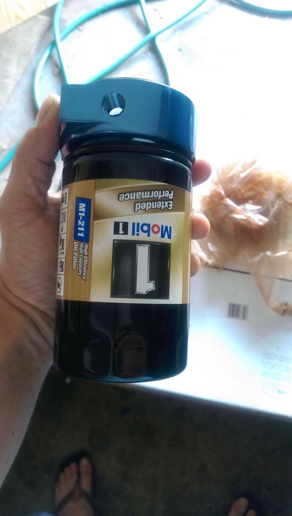
The gauges I used were purchased from glow shift -
http://www.glowshiftdirect.com/. Obviously, any gauge of your choice would work, Initially I wanted to go with AutoMeter, but they are way too expensive and didn’t want to spend 500+ only on gauges. Glowshift has the "gauge package" which includes the gauge and the probe. They also have a 3-in-one gauge, with EGT, Boost and temp, but unfortunately it is too wide to fit in a traditional gauge panel, unless weeks101 comes up with something cool

...
I purchased the lotek pillar from
http://www.gaugepods.com/jeep.html. Unfortunately it only holds 2 gauges. The best alternative to add more I found from weeks101 on this forum (
http://www.sasquatch-motorsports.com/gaugepanel.html), pretty much you replace a vent panel with one of his aluminum gauge pods with vents on the side, in my opinion the best way ever if you don’t want to clutter the interior with additional gauge pods, that may also not look too esthetically pleasing. Those pods are serving 2 functions: air vent (outer) and gauge pod (inner).
Each glow shift electronic gauge comes with a probe, and the probe thread is 1/8 npt. A chart with conversions is here:
http://www.trentonpipe.com/ti_threadformdatachart.html. I'd recommend getting the "elite" series from them, since you can "chain link" the gauges between them much easier, there is a special plug in each gauge and they power up eachother from one gauge to the other and so on, I think they allow max 3 "chained" gauges. They also have a programmable sound and light, so if let's say the oil temp gets too high, or pressure too low, it will trigger the sound alarm and turn on the light, which is a very good feature. They have a min/max recall, so you know for example what was the max EGT temp you ever had. Of course, I jumped the gun when I got mine and went with the non "smart" gauges, the difference would have been maybe 10 bucks/gauge, and it would definitely worth...
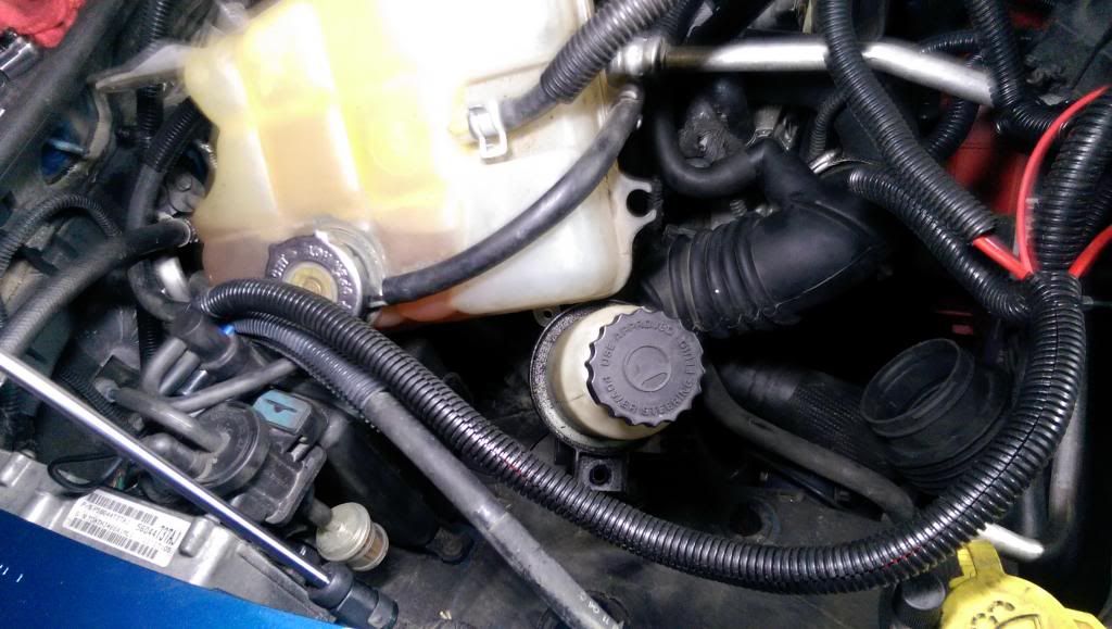
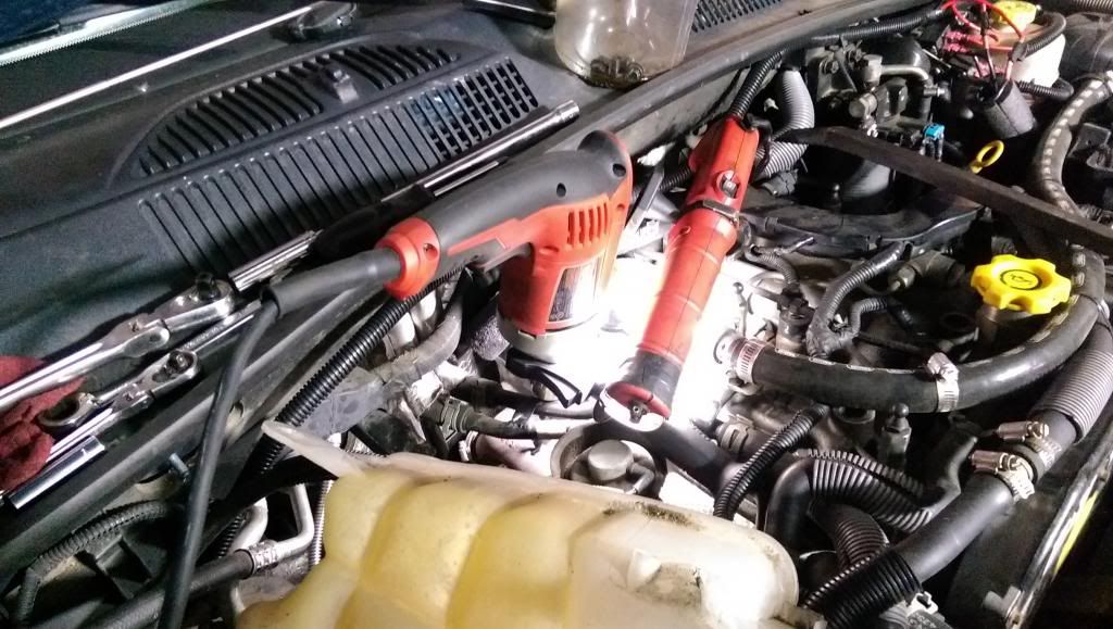
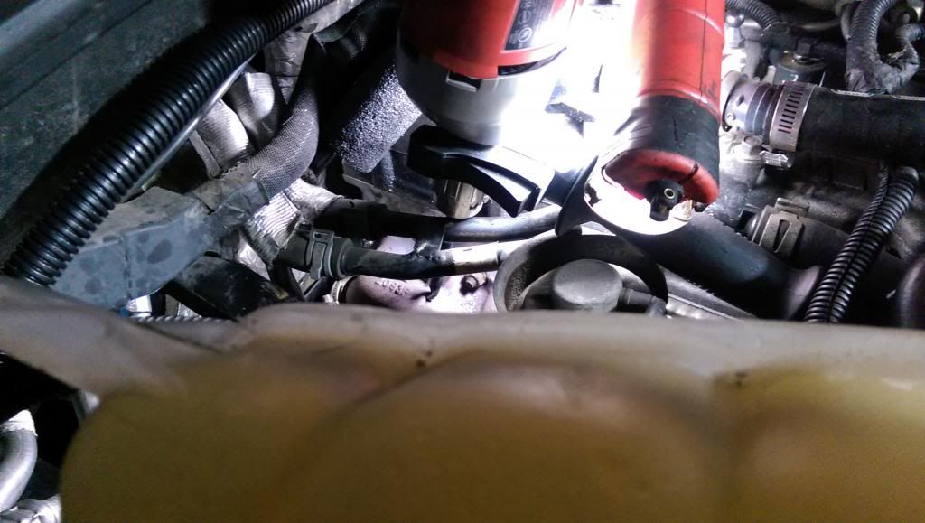
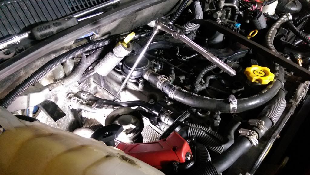
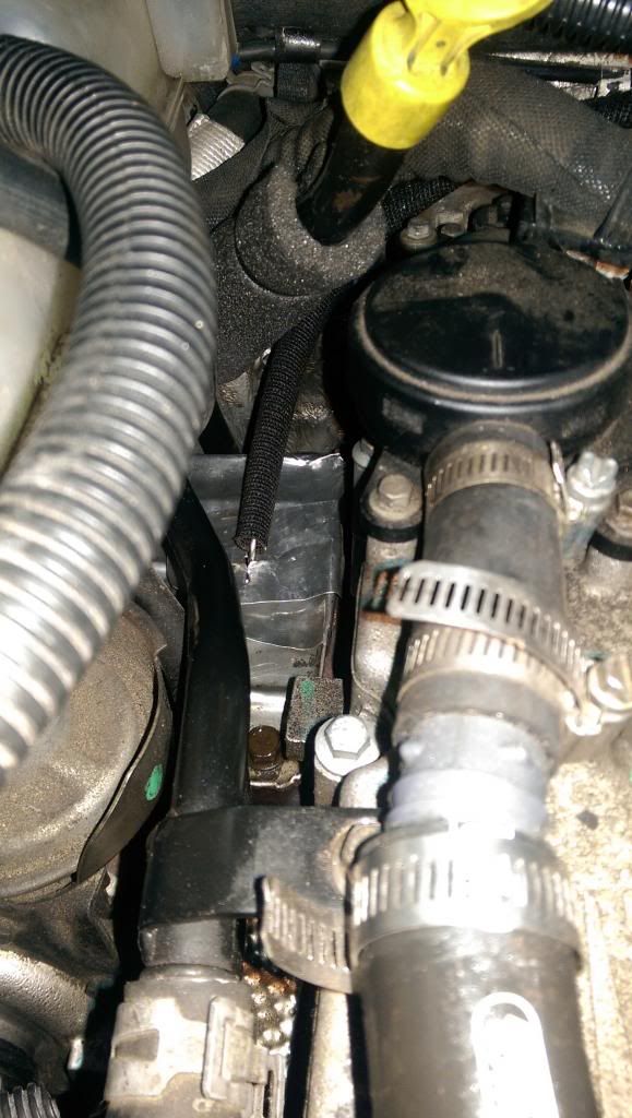
EGT: This is probably the most “involving” installation, since we need to move away the water coolant reservoir that sits sort of above the exhaust manifold and in the way. The easiest way to do this is to disconnect the top nuts the reservoir is secured with and then slide it towards the front of the car. It is a little tricky but not hard. Before removing it, I also moved away the power steering reservoir, to make way for the coolant reservoir. Of course, before all this, remove the airbox and intercooler hose.
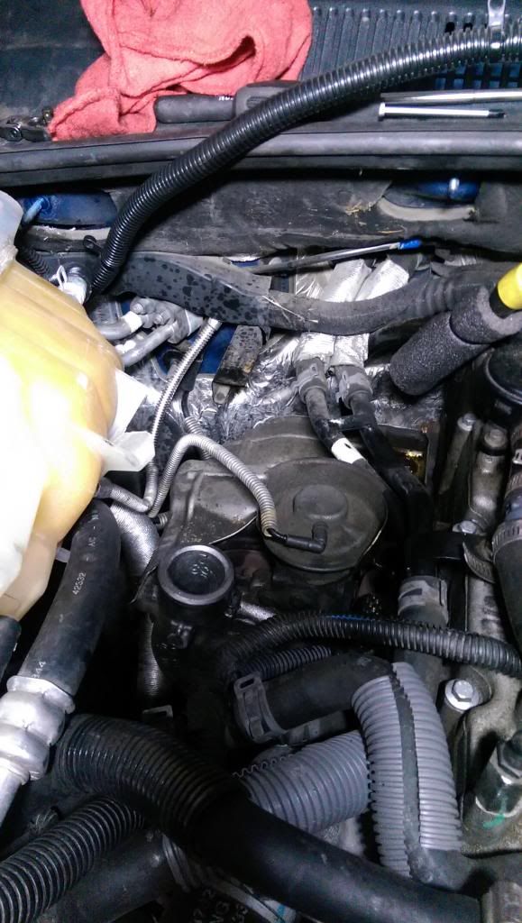
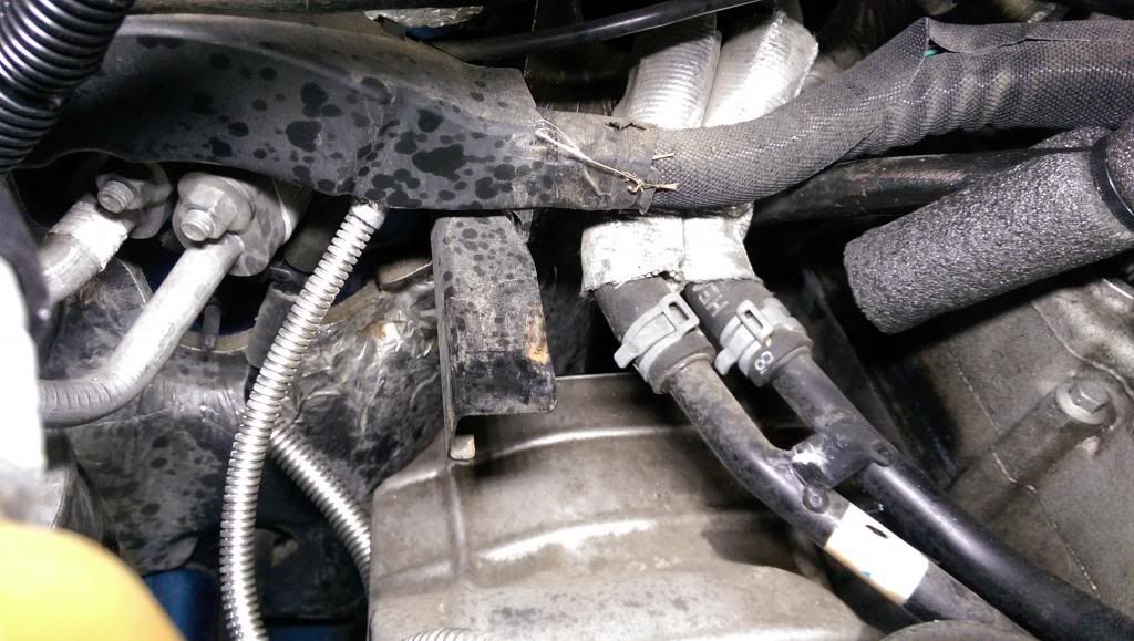
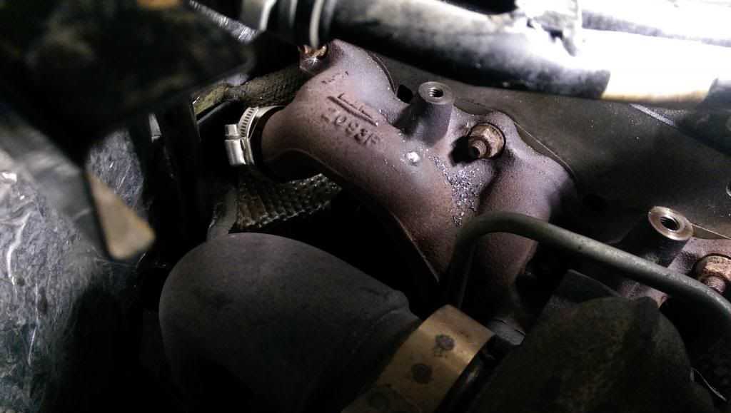
Once this is moved from its position, we have space to remove the heat shield (3 bolts), mounted on the exhaust manifold. 2 of them are on the top and one on the side, like below:
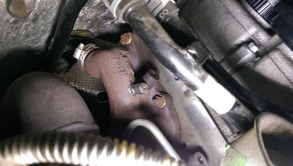
All we need is to find a good spot to drill a hole in the exhaust manifold, where we would install the EGT probe.
Now, many people sort of freak out when is about drilling in the manifold, due to worries that metal shards that result from drilling can get in the turbine propeller through the exhaust and damage it. They advocate for using a lot of grease on the drill bit and on the tap, and constantly wiping it off and refresh it with new one. Nothing wrong with that at all, but I personally think there is no reason for worry if this is done correctly.
Step 1 - find a convenient location for the EGT probe.
Step 2 - use a punch and mark the center of the hole. A light tap is all it needs.
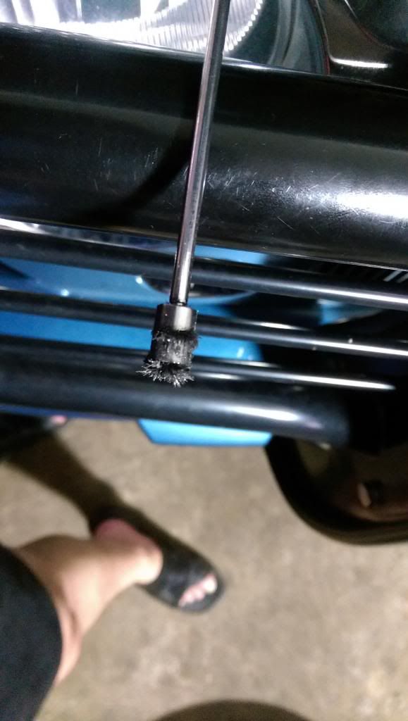
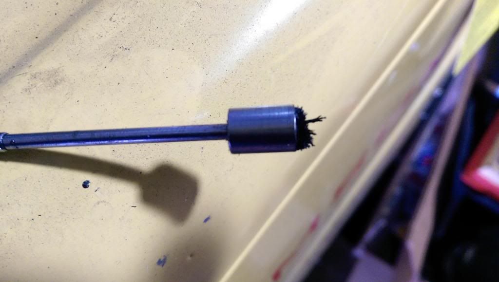
Step 3 - get a telescopic magnet that is smaller in diameter than 3/8. If you don’t have a telescopic magnet, I’d advise getting one, every autoparts store should have some, and the best ones are the cheapest (couple bucks at most), since they are very narrow and the diameter is pretty much smaller than 3/8. This telescopic magnet is the most important part of this job.
We will use this to clean the grinded metal resulted from drilling. We will insert this into the manifold after the hole is made and tapped. I personally like this better than the grease alternative, since if it happens to drop some grease with metal in it inside the manifold, it will be impossible to take it out, even with magnet. Small pieces of grinded metal that we may miss with the magnet won’t hurt the turbo, big shards might.
Step 4 - Drill the hole in the manifold. I used a 3/8 bit, it is pretty closed to the diameter to 1/8 npt and it can be tapped pretty easy. Do not use any grease at all, side of making drilling harder, it is not required. Use common sense when pressing into the drill, low rpm on the drill, decent pressure on the drill bit, pretty much drill slow and with some decent pushing force, but nothing too crazy.
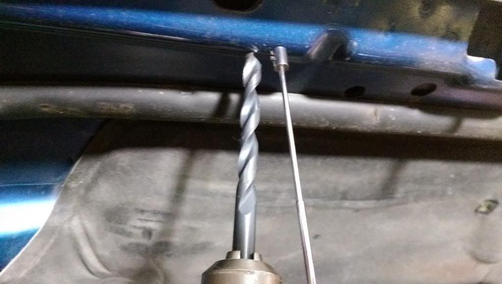
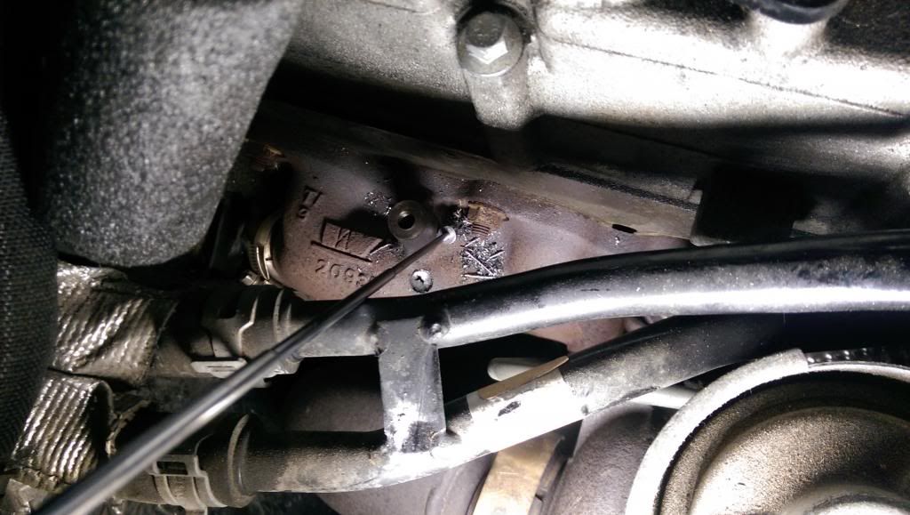
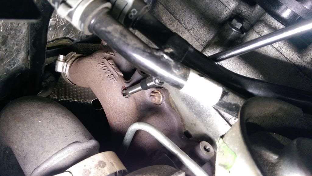
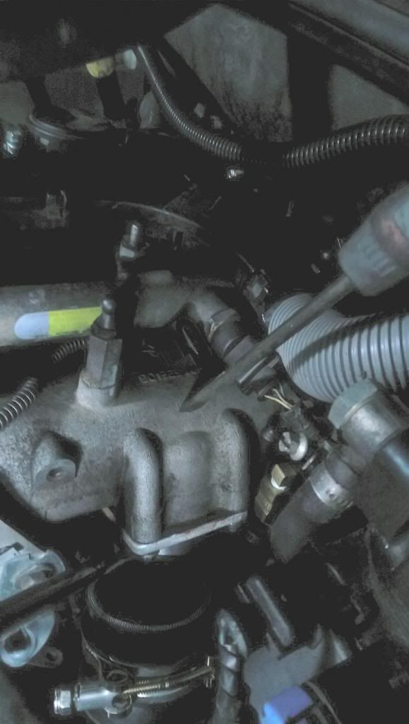
While drilling and getting closer to make it through the exhaust manifold, stop drilling, use the telescopic magnet to clean up the metal shards from drilling. Once you can see the drill started to pierce through the manifold (like in below pic), use very low pressing force on the drill bit, pretty much you want to avoid having the drill bit go through too fast and rip of big shards of metal from the bottom of the hole. In fact, just the weight of the drill could be a bit too much.
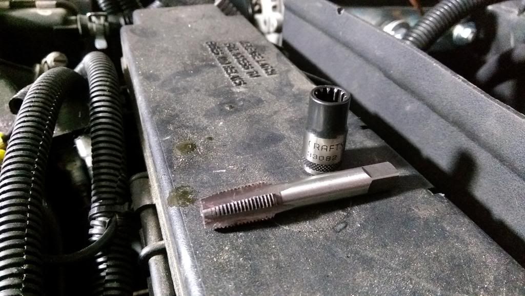
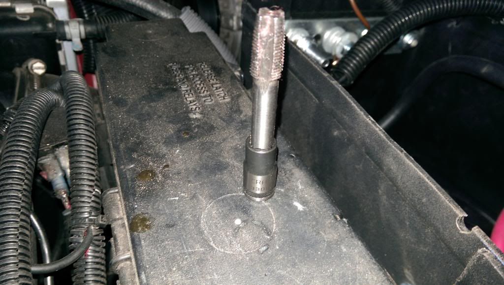
Once the hole is made, clean the inside of the manifold by starting with the center and moving the magnetic telescope as much farther possible. Do this till the magnet won’t have any metal. Then get the 1/8 npt tap and proceed with tapping. I used a socket and an extension to my 1/4 drive, it is easier. Just make sure you are perpendicular to the center of the hole.
Again, be very gentle, turn the tap 180 degrees, reverse 90 degrees, all this very slow. Since you tap, you can use a very small amount of grease on the tap, but not too much, we don’t want grease with metal to drop in the manifold. Once tapping is complete, use the telescopic magnet to do the cleanup. Move it as much as possible side to side, to capture the most of the metal shavings. What's left, will go out through the exhaust. There won't be so much pressure to damage the propeller, so it won't be like a bullet flying out at high velocity.
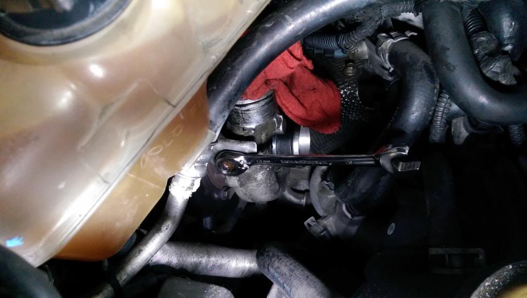
Step 5 – This requires altering the manifold heatshield in such a way to accept the EGT probe going through. With proper measurement, a well thought 1/2 inch hole is all it needs. Remove the EGT sensor from the 1/8 NPT Fitting:
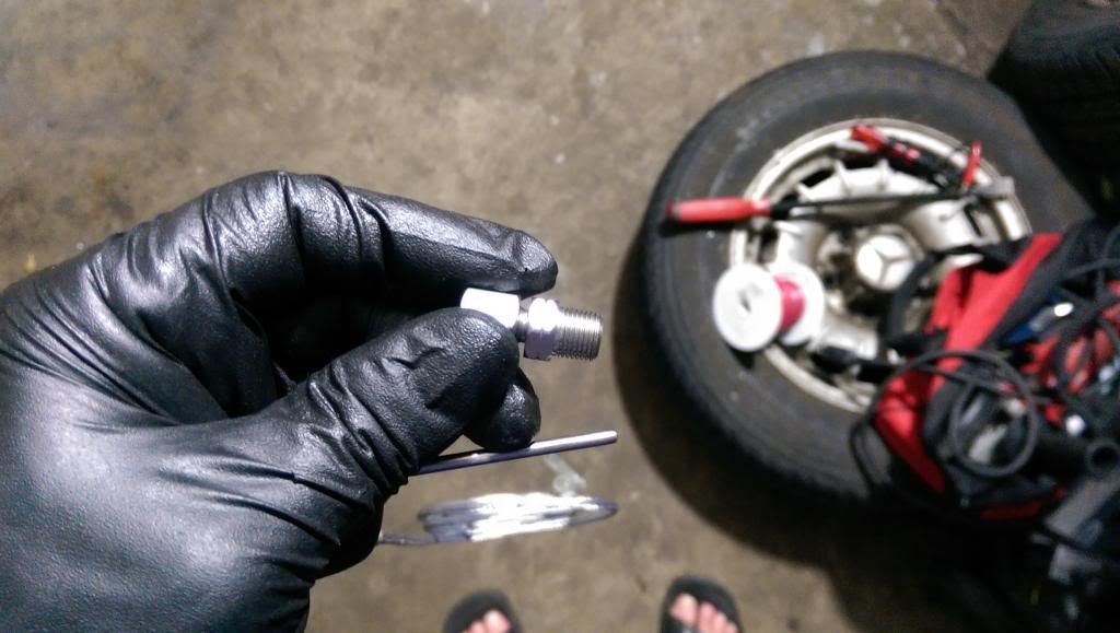
Turn by hand the 1/8 npt fitting in the manifold. Do not use plumbing tape here since it will melt couple minutes after you start the engine. Torque the lower nut so it is safely inside the manifold (careful to not overtorque since it would strip the threads).
After the hole is made in the shield and tested for fitment with the EGT probe, insert the probe into the 1/8 NPT fitting that’s already bolted in the manifold. Torque the fitting till the probe does not turn by hand in the fitting (hold the lower/base nut in place while turning the longer/top nut (do not overtorque just torque so the egt probe will stay in place when trying to twist it by hand left/right). That’s it, do not apply more torque since I felt there is a big risk due to the fact the manifold is pretty thin and stripping the threads is an imminent danger. Optional, you can use some hi temp loom to protect the wires, which I think is not necessary but it wouldn’t hurt either. I also used some aluminum sheet from a used one time use cooking tray, to cover the hole that I made in the heat shield even better (again, I don’t think this is a must, but it may help a bit holding the heat under the shield).
Step 6 – mount the heatshield, mount back the coolant and power steering reservoirs and do the electric connections. The instructions from glow shift are pretty straight forward.
BOOST: There are 2 types of boost: mechanical and electronic. I got for some reason a boost and vacuum gauge (used mostly by gasoline turbos), which is a mechanical gauge. I’d recommend installing an electric gauge, better have only wires than vacuum hoses and wires… Plus there is no need to install a snubber with electrical units. A snubber will prevent oscillations due to valve overlap, drops in pressure, etc, pretty much the needle on a mechanical unit won’t twitch with a snubber. Installing the boost probe/fitting also requires drilling a hole in the valve cover or boost hose/elbow. I chose the valve cover and I drilled a hole right above the elbow kit. Since I have sasquatch (weeks101) elbow kit, this is extremely easy, just remove the hose from the elbow to allow the aluminum shards to fall off and let the gravity do the work.
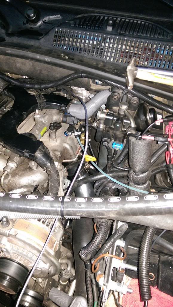
I also inserted a rag through, to make sure it captures all aluminum that results from drilling/tapping. Same 3/8 drill bit, and same 1/8 npt tap. On this boost probe/fitting using some plumbing tape is recommended, due to gaining some thickness in the probe/fitting and having lower temperatures than on EGT, there is no danger this tape would melt.
Oil Temp and oil pressure: Initially, I wanted to use the port that is on the turbo side. After Mass Hole told me about the sandwitch plate from prosport (
http://prosportgauges.com/oil-filter-adaptor-plate.aspx - we need the one with 3/4UNF-16), and after chatting with Ranger1 about pressure and temperature based on his experience, I decided this is the best approach for what I want.
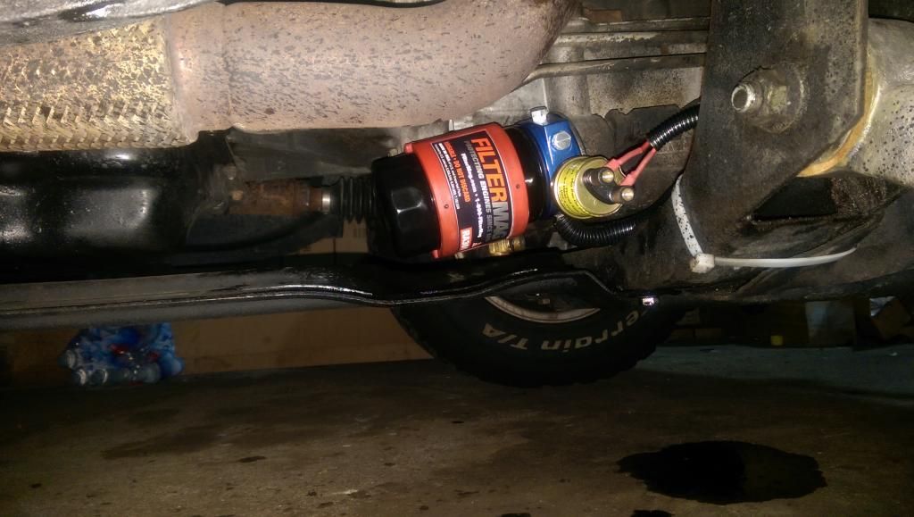
This adapter plate has 4 ports in 1/8 NPT, not that one will use them all, but it makes it easier to position the probes in it. Vibration-wise, it won’t be an issue, if the stock oil probe that is mounted in the area is fine, I don’t see why the other probes won’t be. Pretty much take the oil filter out (I did this when I changed the oil to make it easier), assemble the prosport adapter plate and then the oil filter. Choose a location for the probes before the final assembly, since 2 of the ports must be capped using the supplied 1/8 npt bolts. Use some plumbing tape for all plugs and probes. Add the gauges in the ports you like and this is it…
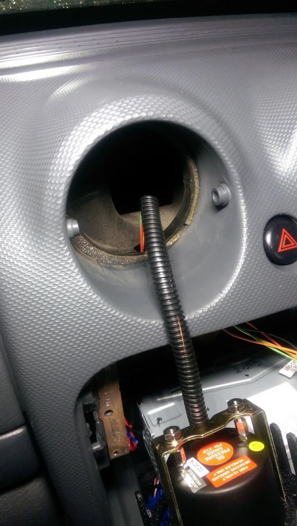
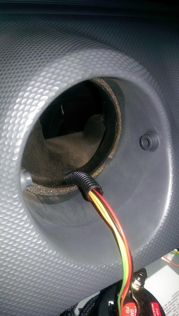
To install sasquatch gauge pods, remove the radio, loosen up the plastic cover over the radio (has one screw on the bottom where the cigarette lighter is, and the everything else is clamps, so once the screw is out, it will come out by gently pulling it towards the trans shifter), slide the trans shifter to “L”. This will allow to slide all those things toward the trans shifter and make enough room for work. Remove the stock vents (just pull them out) then make a small hole on the bottom of the plastic vent, to allow the gauge wires to go through.

One important thing about sasquatch kit, the sides of the pods that are meant to secure the pods on the stock air vents are not equal, and they are not equal since this is how the stock vents are, the idea is to pay attention when you secure the gauge on the pod to do it correctly so it won’t be upside down, or to force the pods into the vents by being 180 degree turned.
Side notes: it is recommended to have a fuse for the gauges, I used one fused circuit for all of them since I did not want to have too much work to do. Pretty much all gauges I added use a permanent +, permanent ground and ignition +. They also have a dimmer wire, which I connected to the ignition + since those gauges are pretty lighten up as dimmed and I don’t have an issue reading them with the sun in the middle of the day. Those 2 + and the – are standard on all glowshift gauges, and they have the same color for any specific wire in between them. The ignition + I used comes from the radio. I pulled a wire through the firewall in the engine compartment (since I use the ignition + for other things, such as efan controller command on, Kennedy pump relay, etc). That ignition wire + turns on a relay, which relay powers up a custom fuse panel from where I turn on custom accessories including gauges. A different fuse panel is powered straight from battery, one of the fuses in that panel is for the gauges permanent +. Both fuse panels are rated to 100 Amps max, those are some pretty sleek fuse panels I got from Napa (I am sure summit Racing has them also), when the fuse burns, it will turn on a red led that corresponds to the burned fuse, so you know where is the issue.


