MPROP
Fuel Quantity Solenoid
Fuel Quantity Valve
Fuel Flow Control Valve
Fuel Control Actuator Flow Control Valve
Fuel Metering Unit
Fuel Pressure Regulator
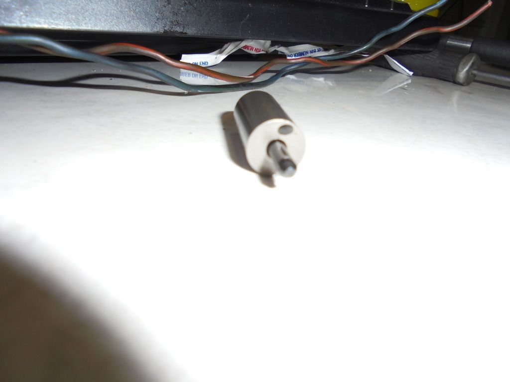
These are just a few of the 20+ terms that I've found, that refer to this guy. All but the last one are all somewhat fairly accurate in describing one or all functions it performs. The last one is inaccurate, as there is no pressure sensing ability or function. That only comes in to play when combined with ECU and Fuel Pressure Sensor.
Here it is with the O-rings removed.
Boredom and curiosity combined again to urge me to destroy a (probably) perfectly good unit, just to see how it's made and how it works.
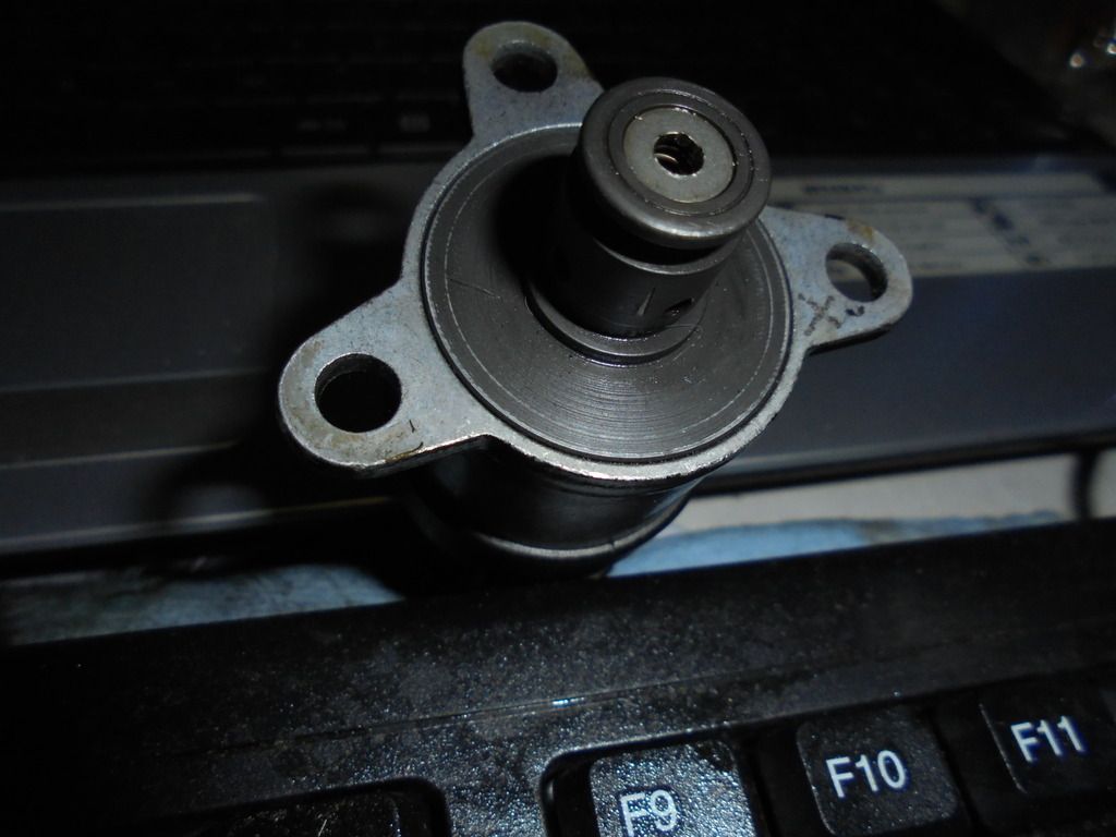
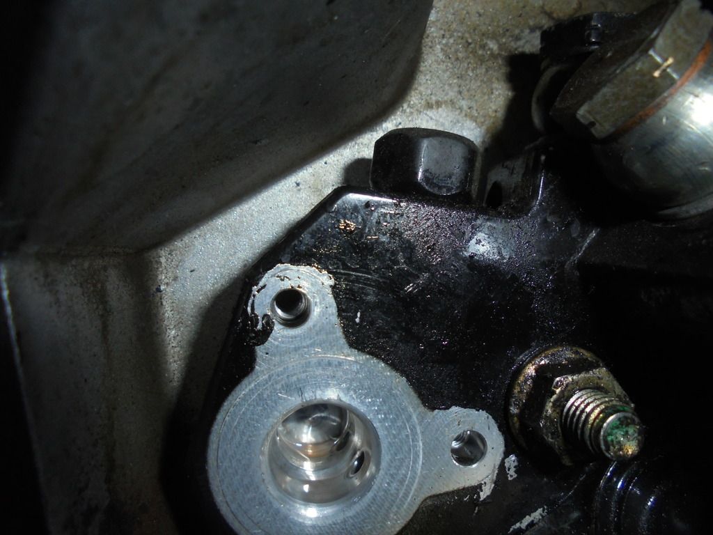
Where this sits, is at the back of the CP3 unit, and is an externally replaceable component in the fuel supply chain.
It is the final component of the low pressure function, and determines how much fuel is delivered to the high pressure pumping plungers.
The method of control is through RMS Pulse Width Modulation signal from the ECM, same as glow plugs as well as the Fuel Pressure Solenoid on the rail.
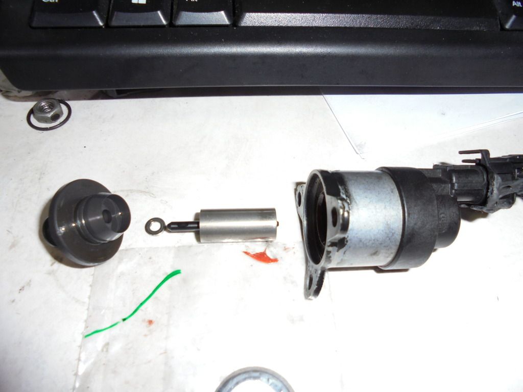
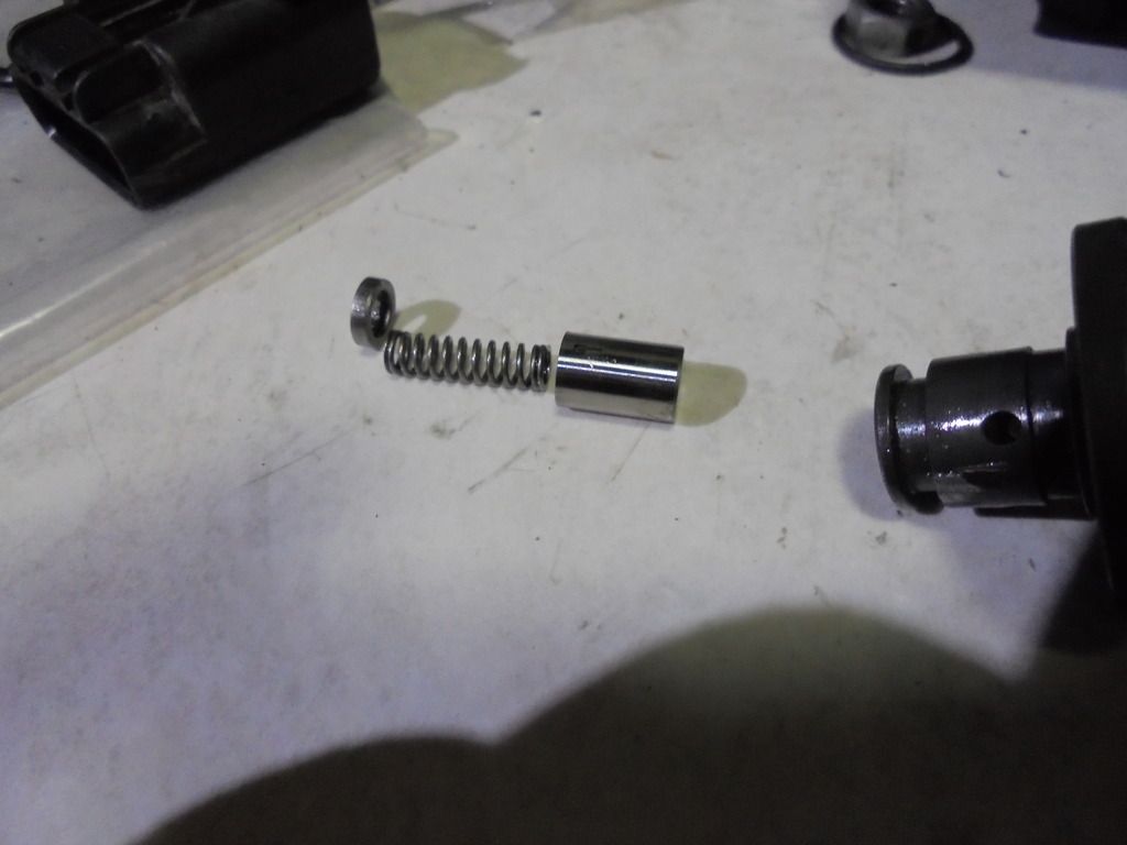
Here are the major parts separated (from left to right)
Valve body on the left, ferrous slug with actuator rod, and travel limit washer, and the magnetic solenoid body on the right.
So basically any description with the terms "Fuel","valve", "Actuator", or "Solenoid" are technically, in part, correct.
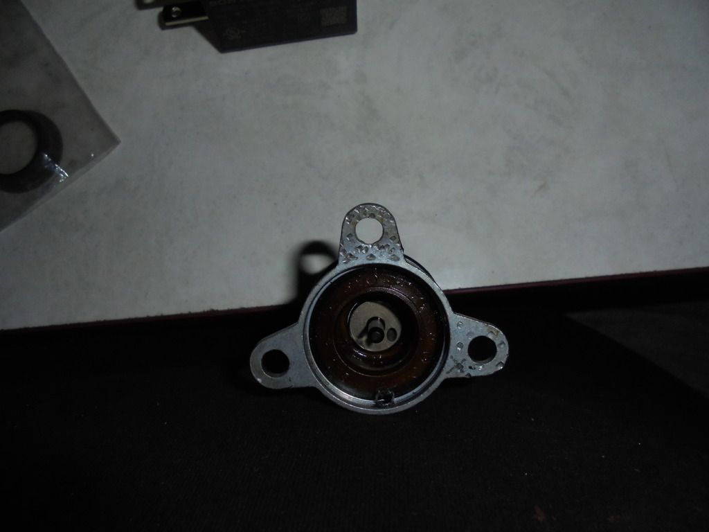
Inside pic of the solenoid. Notice there is no spring behind the ferrous actuator slug.
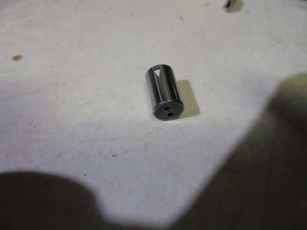
Business end of the actuator slug. Notice the drilled hole. Having a hole here prevents the slug from having hydraulic lock from being immersed in fuel. You will also notice that this end of the drilled hole is oblong. this is because the end of the hole is drilled at an angle. When the actuator moves under spring or magnetic force, this forces the actuator to rotate a little. This helps longevity, by not having the same part of the actuator rubbing on the same part of the tube all the time, back and forth like a file.
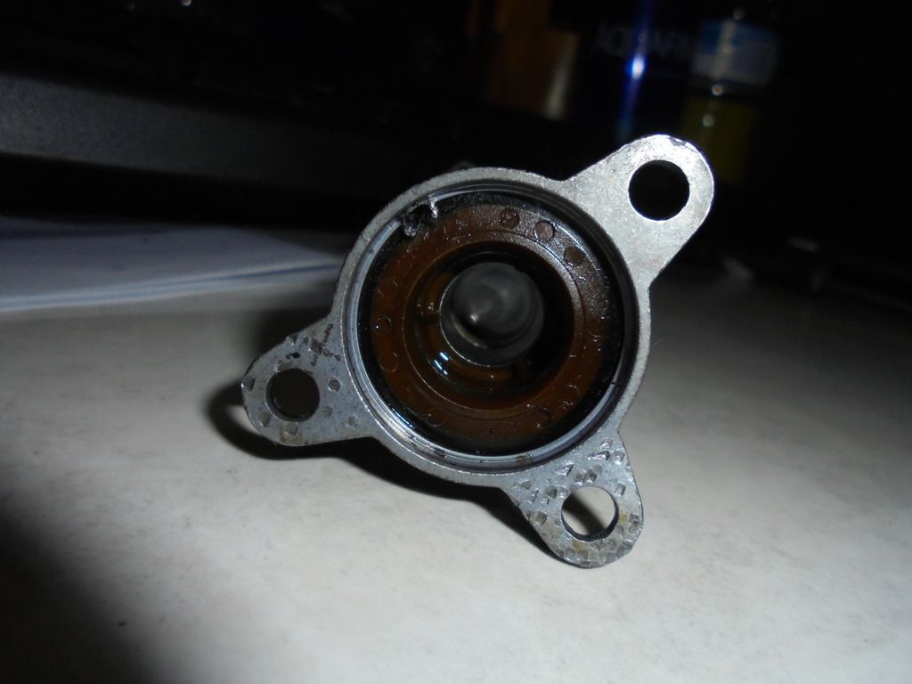
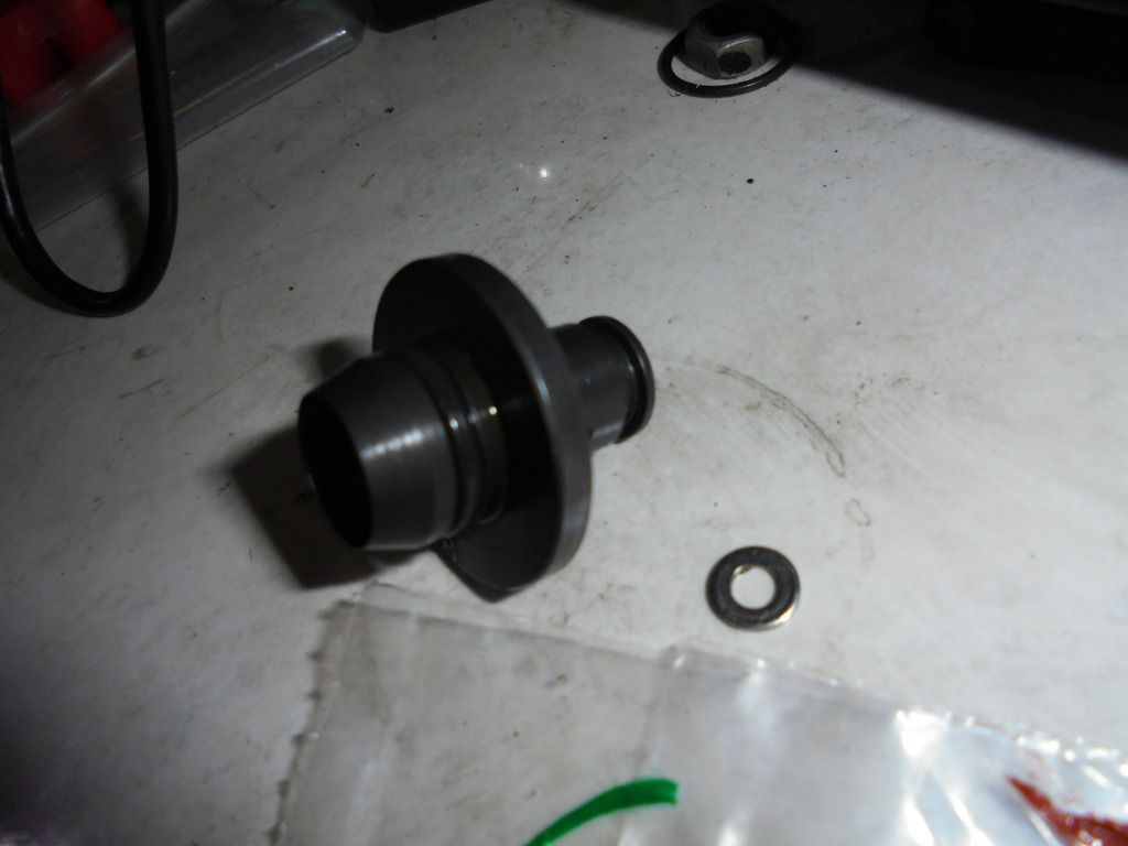
This next little doohickey is the valve where all the critical action takes place. One side of the fat ring part, is the part with the O-rings that protrudes into the backside of the CP3. The other side sits internal to the solenoid body, and the actuator rod hammers back and forth under spring force to open and magnetic force to close the valve.
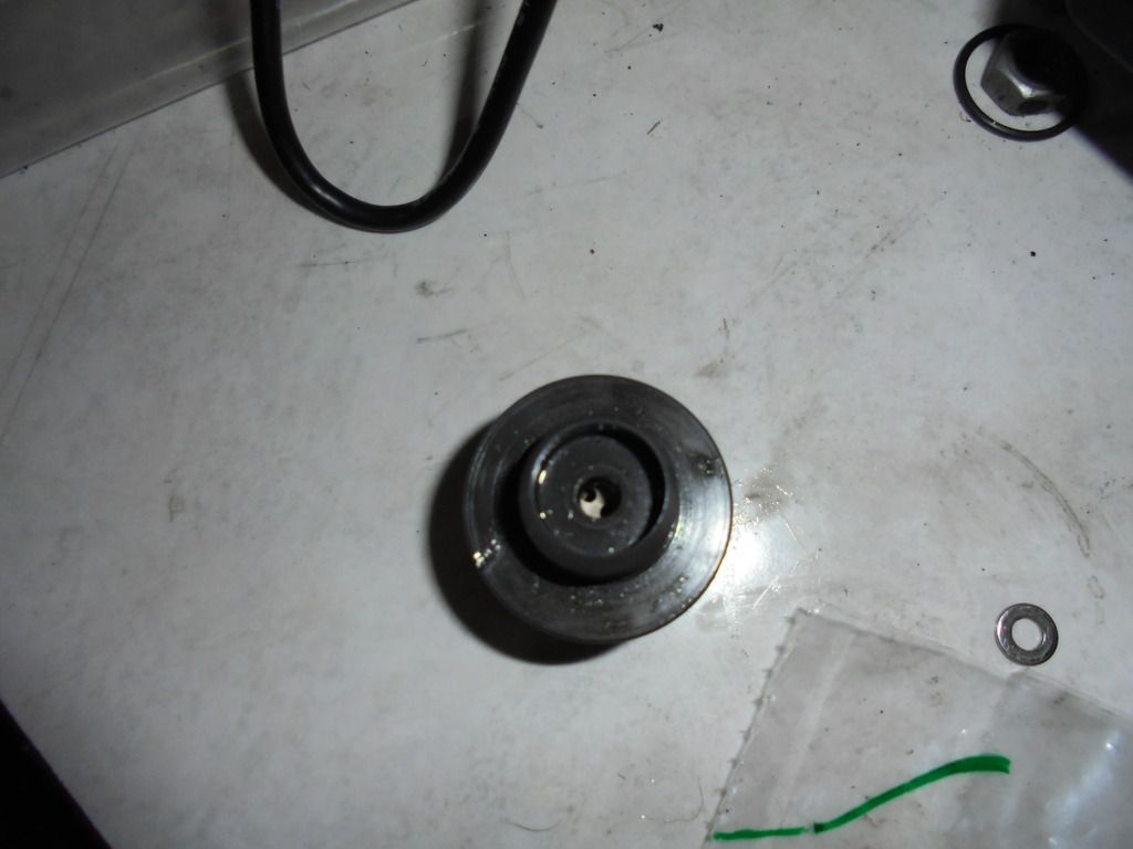
Another view from straight on where the actuator rod goes in. You can see the part of the valve that gets hammered on. The holes you see are simply there to prevent hydraulic lock as it goes back and forth.
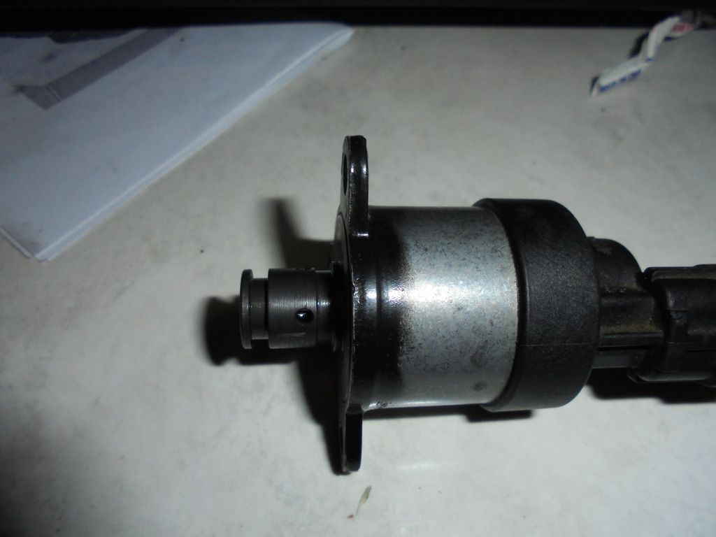
Another picture of the solenoid with the actuator rod inside it, as it would be assembled against the valve body.
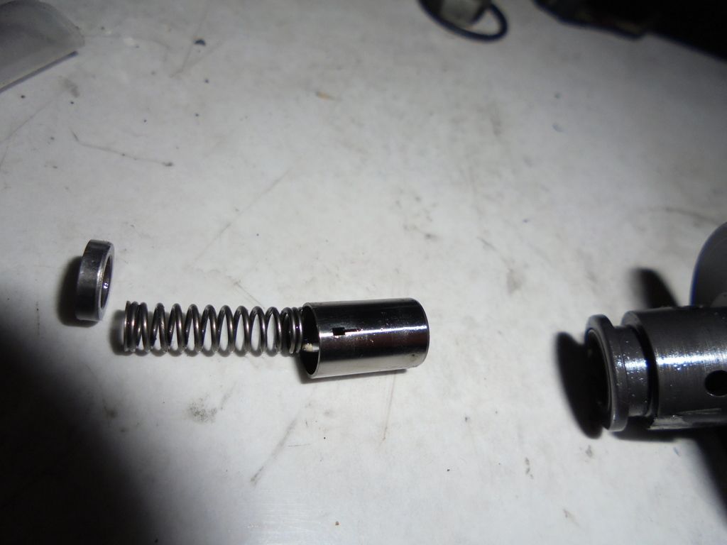
Here you see the valve components disassembled. From Right to left this time:
The valve body as installed has viton O-rings assembled in the grooves on the valve bedy. The holes in the valve body allow the measured amount of fuel from the internal valve to exit and travel through internal passage in the CP3, to the high pressure pumping plungers. This determines the output volume at any given moment, that the CP3 is capable of
The shiny slug looking thing is the actual valve. it's not a slug, it's more of a cup, that the spring to the left of it rides in. All the way to the left, is simply a pressed in cap, with a relief to keep the other end of the spring centered, and have something to push against. The pressed in cap has a hole centered, that allows fuel from the Cascade Overflow Valve to enter the Metering Valve.
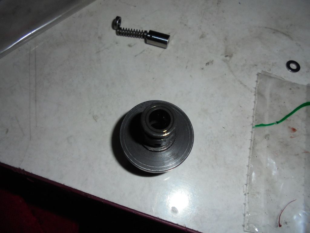
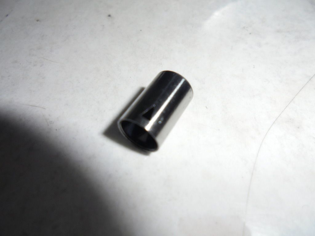
And here is the star of the show.
The Metering valve, showing the nearly microscopic holes that the fuel needs to pass through in proper quantity.
There are different variations of these depending on application.
Some holes are rectangular, some are triangular. There can be 2, 3 or 4 holes.
This one has 2 rectangular holes.
I do not believe it's original but it's the one that was on my vehicle when I bought it.
Another picture showing the port on the other side. I noticed this port is sharply rectangular, where the other side has a tiny machined slot in line with the direction of movement.
When you hear or read of someone who races diesels talk about getting a ported MPROP for better flow, this is the piece they are talking about.
Porting simply provides a larger opening, thus a larger amount of fuel going to the pumping plungers. It raises the pressure and volume potential in the rail.
Usually the result is a crappy idle and more top end horsepower. Injectors seem to object really strongly to having super high pressures but trying to inject just a tiny bit for a normal idle.
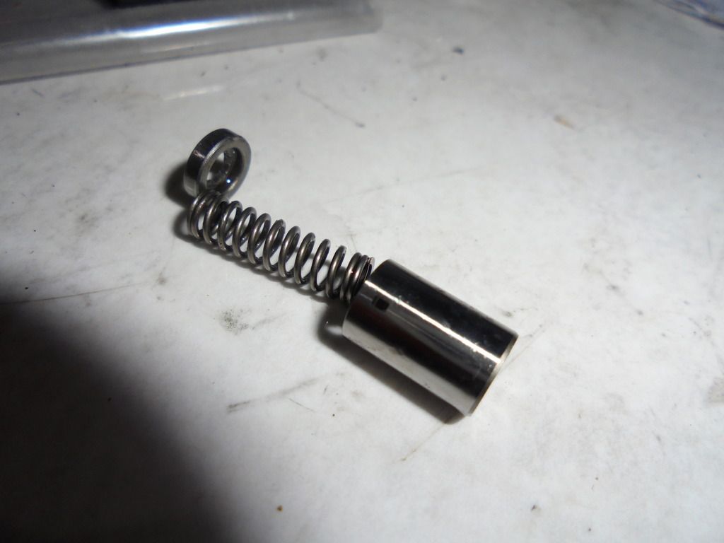
another photo of all the valve components and where they come from
So your basic operation starts from turning the key, at this point there is only spring pressure, and it's holding the valve wide open, to get maximum fuel rail pressure.
Once the vehicle starts, and the ECM kicks in, it looks at the fuel rail pressure sensor, and begins to make adjustments to the amount of fuel that is delivered to the rail, by applying PWM voltage to the electromagnetic servo, which moves the plunger and actuator rod against the other side of the valve cup, reducing the volume of fuel entering the high pressure pumping plungers. If you stomp on the accelerator, it sees that, and responds to the added fuel needs by reducing electromagnetic force, allowing the spring to push the valve cup open further.
These adjustments, like with the Fuel Pressure Solenoid, are being made hundreds of times per second, as ordered by the ECM.
Clean fuel, with augmented lubrication is vital to longevity and proper function.


 but the valve was also sticky in either valve chamber, so at least this one probably wouldn't work with what I have available. If I were able to try it I'm guessing it would probably run, but would most likely pop some codes. With the amount of fuel it allows, it would be working constantly overtime trying to balance the pressure and volume.