Procedure to functionally test starter motor circuits by performing “BYPASS” & Functional Tests at the starter relay plug terminals inside the Power Distribution Center under the hood.
Please provide any corrections or suggestions for improvement. Terms used in this procedure: PDC = Power Distribution Center (See Picture 2)
Tools required to perform the tests in this procedure: 12v DC Automotive Test Light or Voltmeter (multimeter) capable of reading DC voltage (See Picture 1 below)
>>>>**WARNING! Be sure you have the vehicle's gear shift selector placed in the PARK or NEUTRAL position and the parking brake set before performing any of tests listed below on the starter motor.<<<<NOTE: The following tests are simple basic circuit tests from battery to starter motor and control side functional tests, it BYPASSES all normal safety and starter circuit functions including: park/neutral safety switch, clutch interlock switch (if straight shift), ignition switch starter circuit, ECM, etc....A Procedure to perform “BYPASS” test on primary Starter Circuit:1. Remove (unplug) the starter relay No.30 from the PDC under the hood and lay aside. (See Picture 2 below)
2. Using a short jumper wire (12 or 14ga. is best) connect terminal No.s 9 to 10 (30 to 87) in the starter replay plug cavity. (See Drawings A & B below)
3. If the starter motor has a good ground connection back to the battery negative post, the starter motor should spin and engage and spin the engine.
Note: If you have the ignition switch in the "RUN" position when doing this test, and no other problems are present, the engine should start
If the starter motor does not spin when performing the "BYPASS" test above, proceed to test "B":B To test for presence of 12v power at terminal 30 (10) at the starter replay plug cavity.
*you will need a 12v test light or a Multimeter (Voltmeter) that can read DC voltage to test the starter circuits further. 1. Using a 12v test light or volt meter connected to a good ground (Negative Battery post is best) Read/test for voltage at terminal no.10 (30) at the starter relay plug connection, it should light up a test light brightly or read ~12v DC battery voltage if using a volt meter.
2. If your test light does not light up or your volt meter does read 12v at terminal no. 10 (30) on the starter rely plug connection, check the 40-amp main fuse coming directly off the battery 12v+ terminal.
3. If 40 amp fuse is good, check battery connections and wiring from battery + post to PDC for a broke or disconnected wire.
4. If your test light lights up or volt meter reads 12v at terminal no. 10 (30), then check all wiring connections closely at the starter motor for tightness and good connections.
5. If main fuse 40 is good and no wiring issues or bad connections are found and starter fails to spin when starter relay terminals are jumpered, replace starter motor assembly.
If all tests performed in test "B" above are good, proceed to test "C" to test the control circuit functions for starter circuit.
C If Starter Motor spins over and spins engine when performing the "BYPASS" test above.
Procedure to test control circuits for the start circuit signal when turning ignition switch to the "START" position:
1. Using a 12v test light or volt meter connected to a good ground (Negative Battery post is best), touch the test light or volt meter + lead to terminal no. 86 (6) in the starter relay cavity.
2. If 12v is not present at terminal no. 86 (6), using a test light or volt meter check both legs of fuse no. 28 in the PDC (15 amp) to make sure it is good. Should have 12v on both legs of the fuse.
3. If 12v is present at terminal no. 86 (6) in the starter relay cavity, connect the test light ground wire or volt meter negative lead to the 12v positive (+) post of the battery. *Then connect the test probe end of the test light or volt meter to terminal no. 85 (8) in the starter relay cavity. While connected to this terminal, turn ignition switch key to the “START” position, test light should illuminate or volt meter should show 12v.
Note: *This tests the ignition switch and tests that all parameters are met by the ECM and all normal safety and starter circuit functions including: park/neutral safety switch, clutch interlock switch (if straight shift), ignition switch starter circuit, ECM, etc....
Picture 1: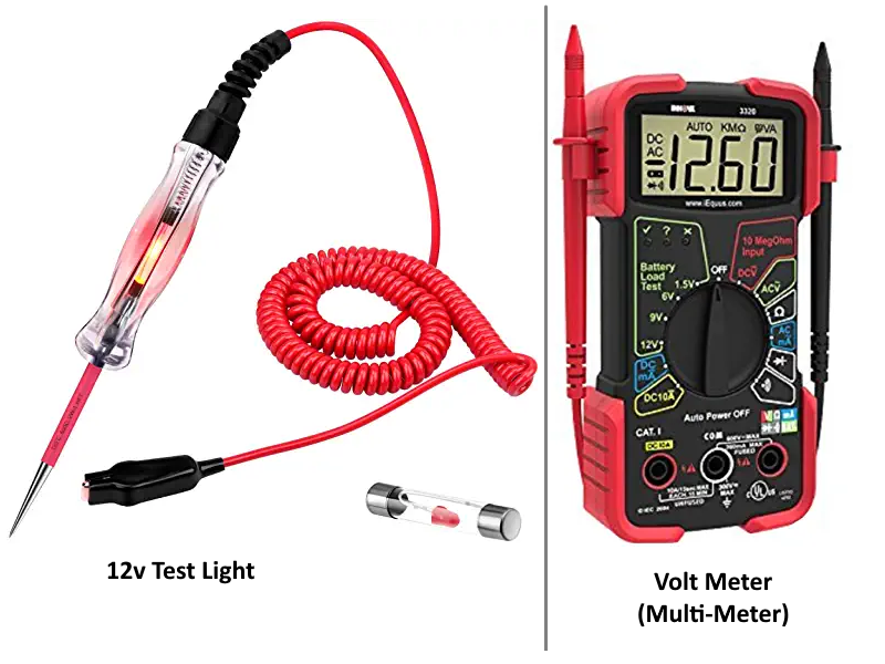 Drawing A:
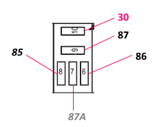 Drawing B:
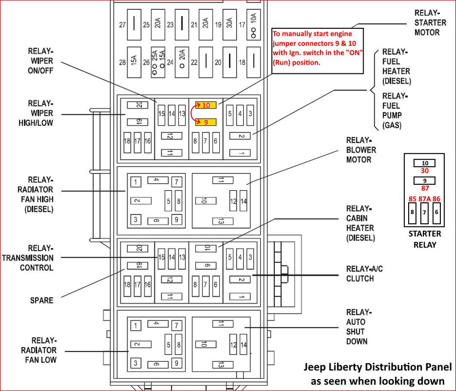 Drawing C:
 Drawing D:
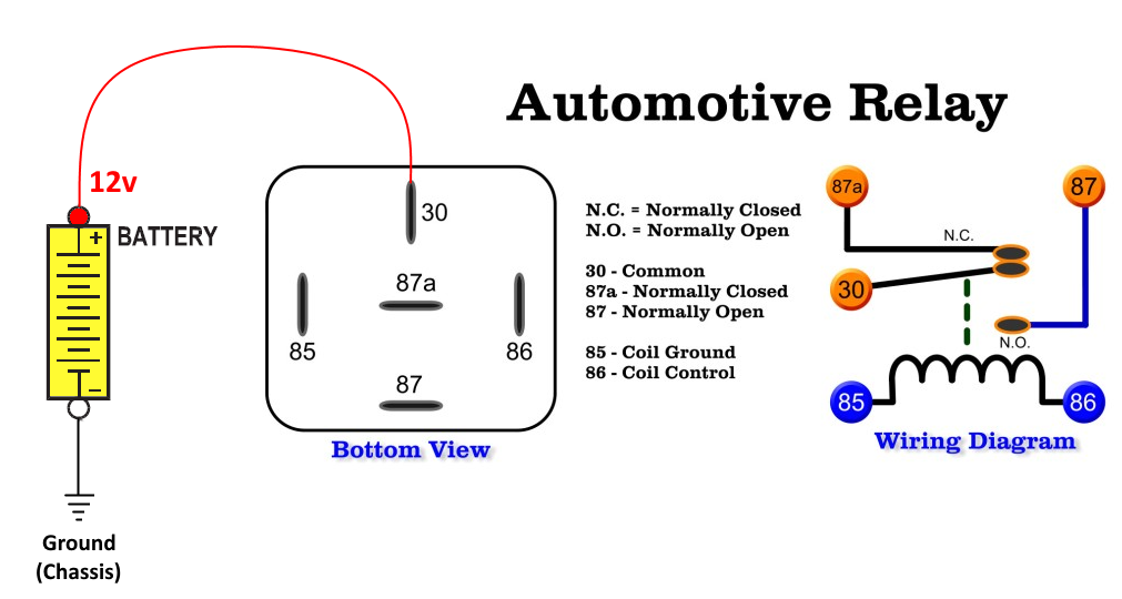 Picture 2:
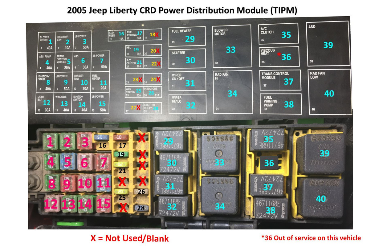
_________________
Supporting Vendor and Moderator of LOST05 Jeep Liberty CRD Limited 
Ironman Springs/Bilstein/Shocks
Yeti StgIV Hot Tune
Week's BatteryTray
No FCV/EGR
Samcos/ProVent
SunCoast/Transgo
Carter Intank-pmp
2mic.Sec.Fuel Filter
Flowmaster/NO CAT
V6Airbox/noVH
GM11 Bld.fan/HDClutch
IronrockArms/wwdieselMount98 Dodge Cummins 24 Valve


