NOTICE: The views on the post are not those of the site and they are not condoned by the site.Another Mod to cross off my list. YEA!
This turns off the ESP completely!
There are a lot of Pics in this one so bare with me.
Any way I will start with a shopping list & tools.
1- 40 Amp relay (5 post) Napa part # LIT 191
(*See Note at bottom*)1- 40 Amp Stock fuse
1- Switch for the dash (I chose a non lighted one)
1- Can of Plasti-Dip
1- Roll of masking tape
11- Female fully insulated wire connectors
2- Male fully insulated wire connectors
2- Male partially insulated wire connectors
2- Butt connectors
2- Loop connectors
1- In-Line 5 Amp fuse
1- Roll Electrical tape
A whole bunch of wire... 5 different colors
2- 9 inch long very small bare coper wire. (You could strip off the insulation from one of the above and then peel off a single wire)
1- 3/8" Plug
1- 3/8" Rubber washer (I made one from a piece of inner-tube)
1- 3/8 " Grommet
1- tube ATV Black silicon sealant
TOOLS:
Wire strippers/crimper's
Drill, 1/8" bit
Small round file
Hacksaw or scroll saw
Small flat file
Long sharpened coat hanger for an awl
Patience and a lot of it!
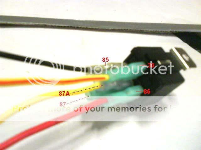
Below is a Wire color chart followed by a diagram.
It is the best I could make. SO LIVE WITH IT!
Relay activation:
Red wire for the power to "activate" the relay.
Black wire from the relay to the dash switch.
White wire to ground the dash switch.
Circuit wires:
Yellow w/Red stripe for the "always on" wire from the original fuse post in the fuse box, to the "remote" fuse, then to the relay.
Yellow for the return wire from the relay to the other original fuse post.
(Note: The 87 post on the relay is not used.) (Caution: The 87 post has power to it when the relay is activated. Cap the post if you do not use it!)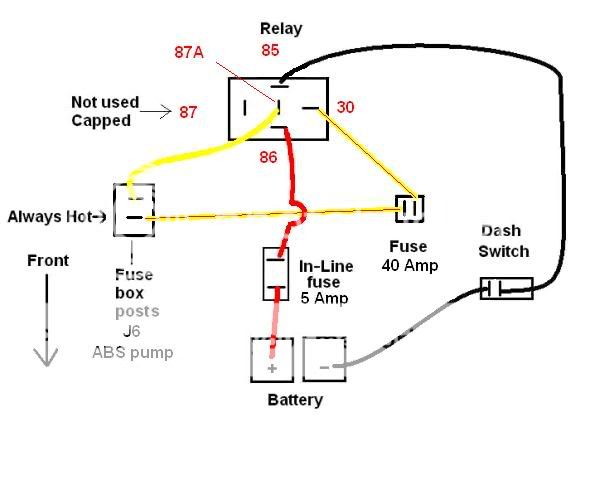
Now for the fun stuff...
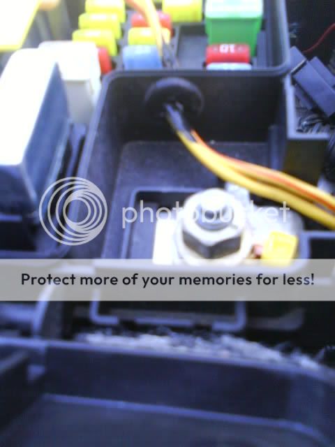
The first thing I did was to disconnect the negative battery cable. Then I drilled a hole in the fuse box. I was very concerned with the possibility of water getting in, so I took extra care to not damage the seal around the top. I first drilled a 1/8" hole and then made it bigger with the round file till it was 3/8" round.
This is where the Plug with the rubber washer will go when I have service done. And also where the Grommet and wires will go when I am playing.

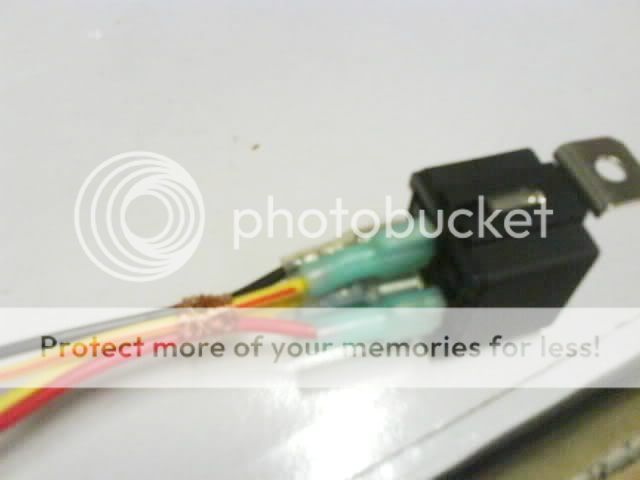
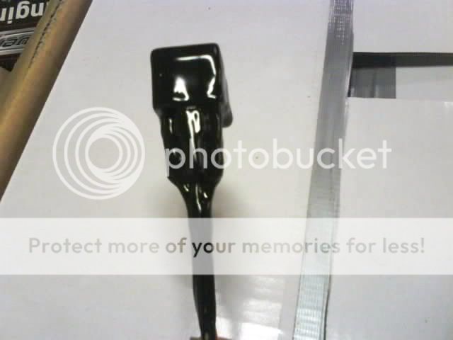
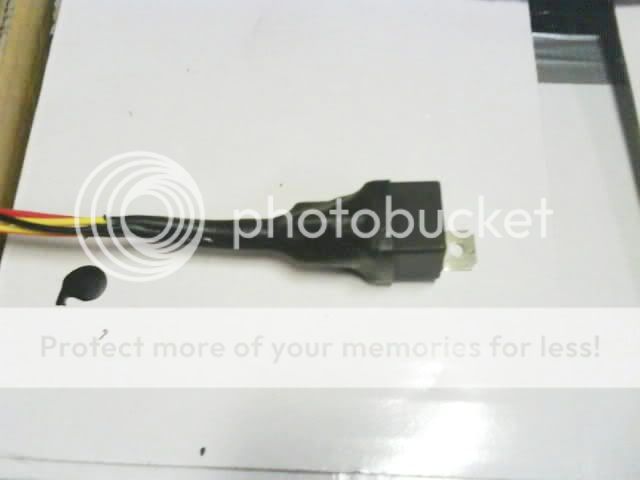
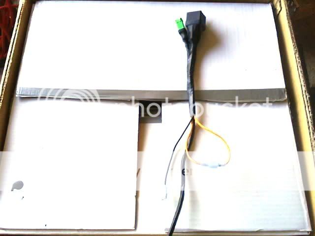
The next thing I did was to make a wire harness for the relay.
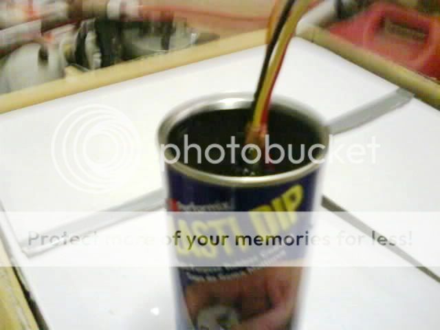
After I tied the wire together I dipped the whole thing into the Plasti-Dip.
(Follow the directions on the can) I put 4 layers on it.
I did this for two reason; 1 was to create a water barrier, 2 was to make a plug-in.
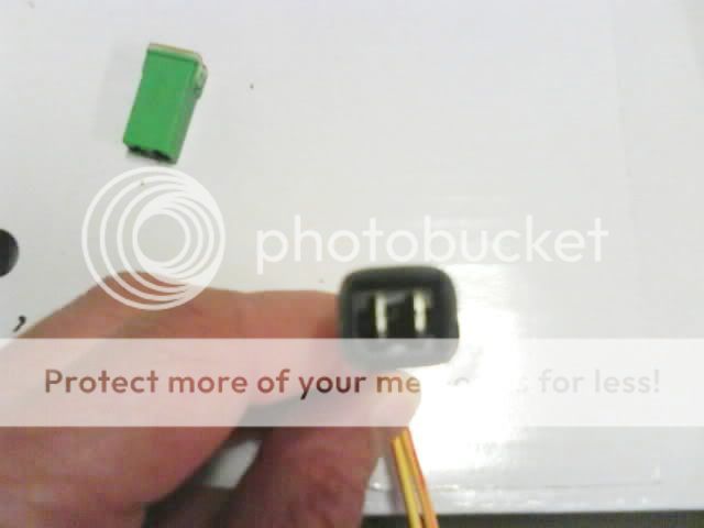
This is what it looked like after it dried.
Then I cut off the Plasti-Dip from the top of the relay. Voilà Plug-in.
Next I did the same to the fuse, however on the fuse I used masking tape to cover the part I did not want the dip on.
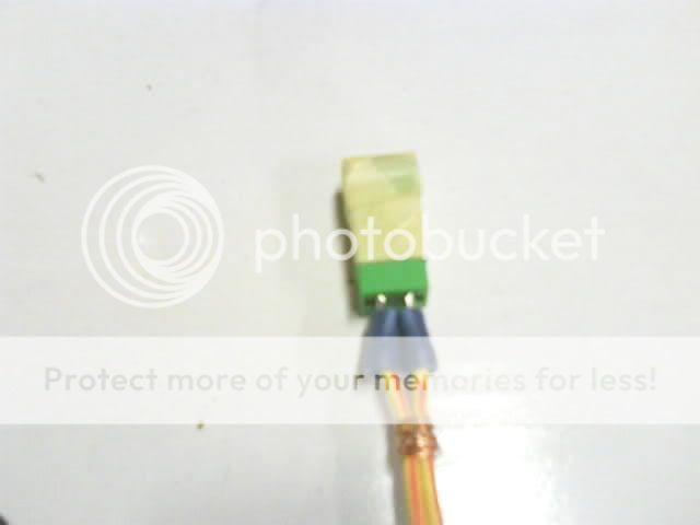
After I cut off the excess.
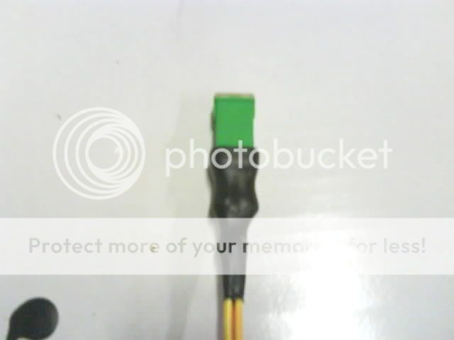
Plug in...
Then I wrapped the 2 together with electrical tape and connected the Yellow w/Red striped wires.
(One from the Relay and one from the fuse.)
On the drivers side fire-wall there is a stud used to hold a hanger for the stock wire harness. I pulled the hanger off the stud and put on the Relay/ Fuse bundle.
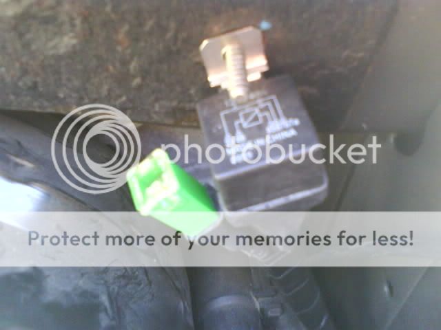
Here is what it looks like with the stock wires back in place.
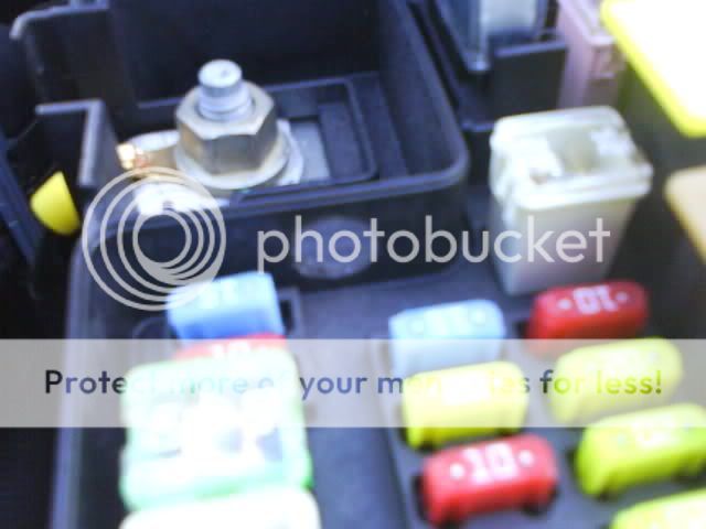
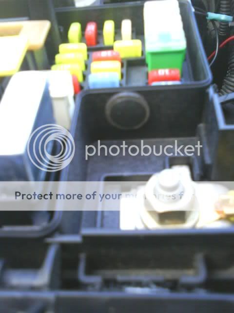
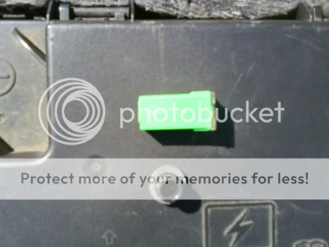
Next I removed the negative battery cable, opened the fuse box, and removed the J6 fuse.
(Caution: The Post I have circled in this Pic always has power to it. Even with the rig turned off!) 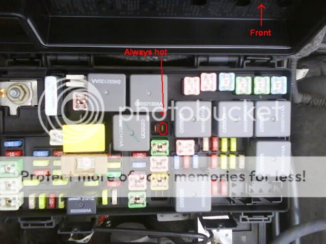
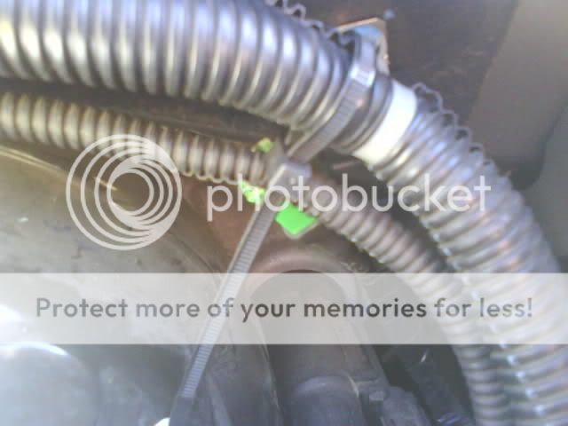
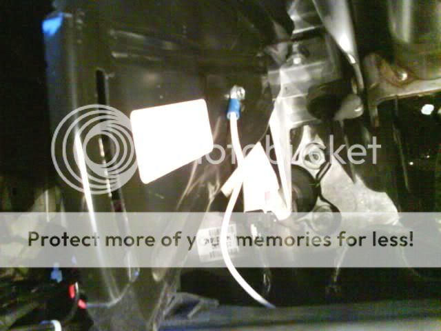
I ran the wires through the grommet and then connected the Female fully insulated wire connectors on the ends. You have to do it this way or the connectors will not fit through the grommet.
(Red striped from the "remote" fuse and Yellow from the relay.)
Then I sealed the grommet with the Black ATV silicone.
I routed the wire inside the fuse box and connected them to the J6 fuse posts.
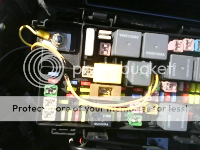
Note the wire with the red stripe goes to the "Always on" post.

Now I ran the wire into the rig for the switch.
I used the sharpened coat hanger to poke a hole through the rubber grommet where the factory wires come through the fire-wall. I taped the Black wire to the coat hanger so it would go through at the same time.
Sorry no Pic it is just too dark under there.
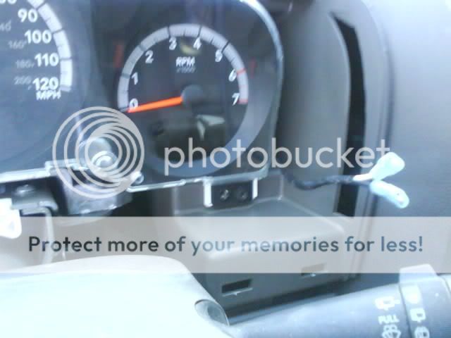
Once through the fire-wall I taped the Black and White wires together. Then neatly ran the wires up next to the gage cluster and out on the right side.
The White wire comes down just to the left, of the center of the foot well, to a grounding point. There really isn't much under there to ground too, so I drilled a hole into the metal plate and used a self-tapping metal screw, to attached the wire.
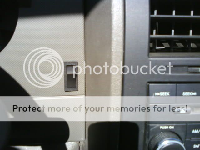
I removed the gage cluster bezel and made the hole for the switch on the right side of the steering wheel.
To complete the circuit I ran the Red wire from the relay to an in-line 5 Amp fuse, then connected it to the positive terminal on the fuse box.
No Pic here either because I forgot to get one before I taped everything up.
I keep these in the glove box for service visits.
Any way...
The relay and switch work great!
When the dash switch is in the "off" (Open circuit) position the power comes from the "always on" post in the fuse box, through the Yellow w/Red striped wire, to the "remote" fuse, out of the "remote" fuse, over to the relay, through the relay, and back down the Yellow wire, to the other post in the fuse box.
Everything functions as normal.
When you turn the dash switch to the "On" (Closed circuit) position the relay turns off the power from the Yellow w/Red striped wire. Disabling the ESP, ABS, and BAS systems. The lights on the dash will light up letting you know it is disabled.
The braking ability of your ride should work as normal except the ABS and the traction control, will not work.
To get the system back to normal, turn the dash switch to the "Off" (Open circuit) position. Then you will need to turn the rig off, and restart it. Drive it a few feet forward and the dash lights will go off.
All is back to normal.
(*Note: Since the Nitro uses a 40 Amp fuse, I was not comfortable using a 30/40 relay, which is much more common and cheaper. The first number "30" is the amperage the relay is designed to handle through the "87A post" which is the one used for this Mod. The second number "40" is the amperage the relay is designed to handle through the "87 post" which is not used in this Mod.*)Do this at your own risk.It is illegal to have the ESP disabled on a vehicle, while it is being driven on the road.
I take no responsibility for any modifications you decide to make to your ride, or the results of those modifications. I do not advise ever using this anywhere but at the race track or off road, and NEVER use this in bad weather, because your ability to control the vehicle in slippery conditions will be greatly impaired.