So per recommendations from others in the forum I found and replaced my driver side wheel bearing, TimKin brand for $200.

Here are a few notes I thought might help others.
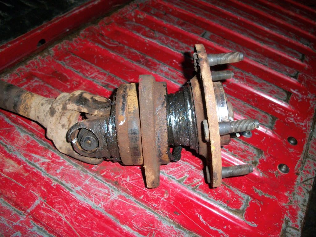
 Front hub and wheel bearings:
Wheel bearing cartridges are sealed assemblies that can not be lubricated.
They should have almost zero play.
With the front wheel still jacked up by the control arm, grasp each wheel, holding it first at the sides, then at the top and bottom. See if you can rock the wheel in and out, you shouldn't notice any looseness.
Also rotate the tire by hand. Any roughness or noise from the bearings will also tell you the bearings are worn or damaged.
If the bearing needs to be replaced, the right hand side (with ABS) part number is 52128692AE (or AA or AF). The left is 52128693AE (or AA or AF).
You need an External TORX socket size E-14 to do it.Jeep 06 Liberty KJ FRONT 2 - 17 pg 64
HUB / BEARING REMOVAL1. Raise and support the vehicle.
2. Remove the tire and wheel assembly.
3. Remove the caliper adapter (Refer to 5 - BRAKES/HYDRAULIC/MECHANICAL/DISC BRAKE CALIPERS -REMOVAL). -
CAUTION: Never allow the disc brake caliper to hang from the brake hose. Damage to the brake hose will result. Provide a suitable support to hang the caliper securely.
4. Remove the disc brake rotor (Refer to 5 - BRAKES/HYDRAULIC/MECHANICAL/ROTORS - REMOVAL).
5. Remove the wheel speed sensor (Refer to 5 - BRAKES/ELECTRICAL/FRONT WHEEL SPEED SENSOR -REMOVAL).
6. Remove the bracket securing the wheel speed sensor wire.
7. Remove the axle shaft nut. (if equipped with four wheel drive)
8. Remove the three mounting bolts for the hub/bearing assembly.
9. Remove the hub/bearing.
INSTALLATION1. Install the hub/bearing assembly to the vehicle.
2. Install the three mounting bolts for the hub/bearing. Tighten the bolt to 130 N·m (96 ft.lbs.).
3. Install the axle shaft nut. Tighten the nut to 135 N·m (100 ft.lbs.). (if equipped with four wheel drive)
4. Install the bracket to the wheel speed sensor wire.
5. Install the wheel speed sensor to the hub. Tighten the bolt to 13.5 N·m (10 ft.lbs.) (Refer to 5 - BRAKES/ELECTRICAL/FRONT WHEEL SPEED SENSOR - INSTALLATION).
6. Install the disc brake rotor (Refer to 5 - BRAKES/HYDRAULIC/MECHANICAL/ROTORS - INSTALLATION).
7. Install the disc brake caliper adapter. Tighten the nut to 135 N·m (100 ft.lbs.) (Refer to 5 - BRAKES/HYDRAULIC/
MECHANICAL/ROTORS - INSTALLATION).
8. Install the tire and wheel assembly. (Refer to 22 - TIRES/WHEELS/WHEELS - STANDARD PROCEDURE
SENSOR-WHEEL SPEED-FRONT REMOVAL1. Disconnect the front wheel speed sensor wire connector that is located on the inboard side of the respective
wheel house.
2. Raise and support the vehicle.
3. Remove the tire and wheel assembly.
4. Remove the caliper adapter. (Refer to 5 - BRAKES/HYDRAULIC/MECHANICAL/DISC BRAKE CALIPER
ADAPTER - REMOVAL).
CAUTION: Never allow the disc brake caliper to hang from the brake hose. Damage to the brake hose with
result. Provide a suitable support to hang the caliper securely.
5. Remove the disc brake rotor (3). (Refer to 5 -RAKES/HYDRAULIC/MECHANICAL/ROTORS - REMOVAL).
6. Remove the wheel speed sensor mounting bolt to the hub.
7. Remove the wheel speed sensor wire from the hub/bearing.
8. Remove the wheel speed sensor wire hold down (4) from the knuckle.
9. Remove the wheel speed sensor wire (1) thru the wheel well.
10. Remove the wheel speed sensor (2) from the vehicle.
INSTALLATION1. Install the wheel speed sensor (2) to the vehicle.
2. Install the wheel speed sensor wire (1) through the wheel well.
3. Install the wheel speed sensor wire (1) to the hub/bearing.
4. Install the wheel speed sensor wire hold down (4) to the knuckle.
5. Install the wheel speed sensor mounting bolt to the hub. Tighten the mounting bolt to 13.5 N·m (120 in. lbs.).
6. Install the disc brake rotor (3) (Refer to 5 - BRAKES/HYDRAULIC/MECHANICAL/ROTORS - INSTALLATION).
7. Install the disc brake caliper adapter. (Refer to 5 - BRAKES/HYDRAULIC/MECHANICAL/DISC BRAKE CALIPER
ADAPTER - INSTALLATION).
8. Install the tire and wheel assembly (Refer to 22 - TIRES/WHEELS/WHEELS - STANDARD PROCEDURE).
9. Reconnect the front wheel speed sensor wire connector to the inboard side of the wheel house being worked on.