Again, sorry for the delay. Started a new job and didn't want to just upload my handwritten scribbles.
This info is common knowledge for many but I'll assume very little experience for readers with my description:
It's still a fairly basic electrical schematic for adding some low amperage accessories to your vehicle whilst keeping it as separate as possible from the factory wiring. If you're running higher amperage items like spot lights, fridge, etc, then you'd use a dedicated relay circuit per accessory (the left side of diagram). It's common best practice to use a correctly selected relay to operate any new electrical accessories. A perfect example being where spot lights are operated by a relay activated via fog lights or high beam, just energize the relay coil from the active connection of the device you want to use as the trigger. Always place a fuse close to the battery and a kill switch isn't a bad idea either.

In my case I've mounted a high amperage self resetting circuit breaker straight off the battery so I know any short circuits beyond there will be protected.

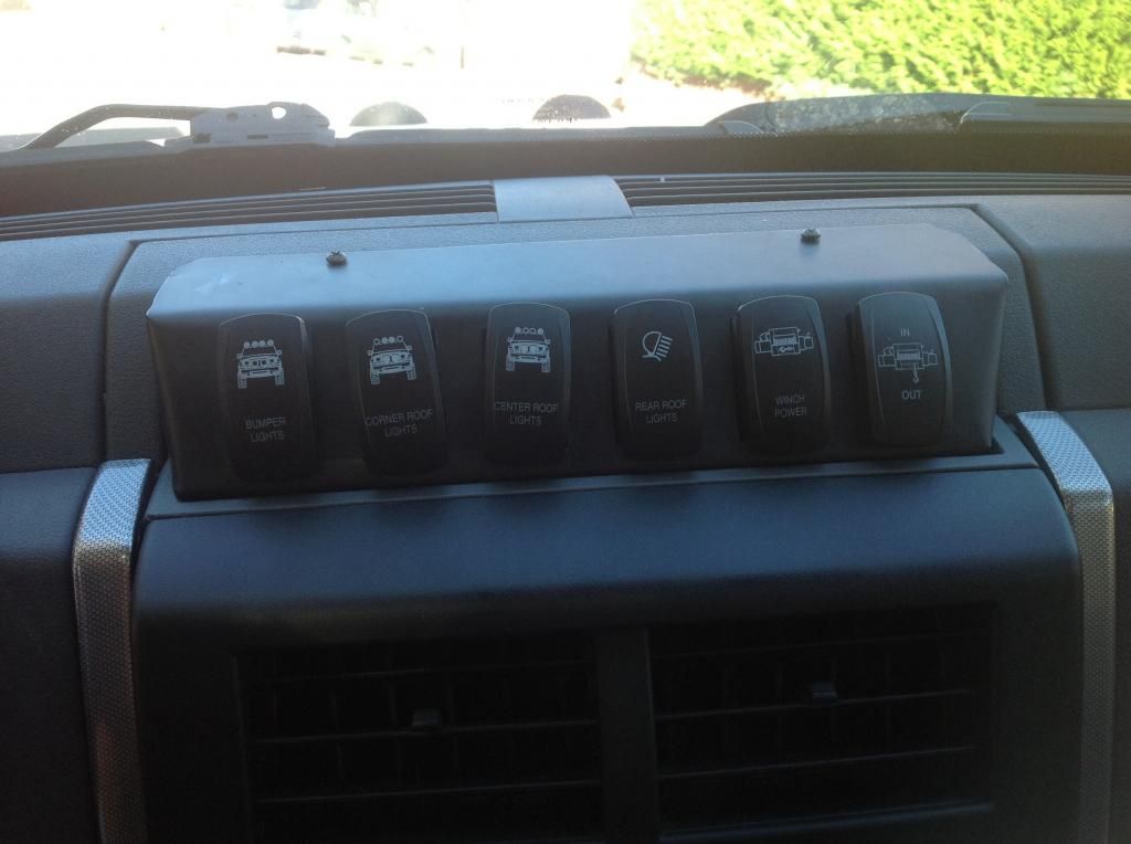
The accessory switch is a common 30A 12volt rocker with LED indicator but now there are some great custom labelled switches selling very cheaply.

Relay is a common 30A horn relay.

Low voltage override is a common dual pole dual throw toggle switch.

I used a missile switch cover on this as I didn't want it activated by accident.

Low voltage override indicator LED is a 12v flashing type.

Hope this helps someone.

PDFs of the circuit operations:
https://drive.google.com/file/d/0B-3SPy ... sp=sharinghttps://drive.google.com/file/d/0B-3SPy ... sp=sharinghttps://drive.google.com/file/d/0B-3SPy ... sp=sharinghttps://drive.google.com/file/d/0B-3SPy ... sp=sharingHere's a gif showing the same thing:
https://drive.google.com/file/d/0B-3SPy ... sp=sharing


 I was thinking the exact same thing..