It lines up every 3rd rotation, and is back to original position with the cams at every 6th rotation.
Now - about the timing of the fuel pump. The rail is ALWAYS full of fuel, what you are doing is managing the pressure waves with the fuel pump timing. This is a 4 cylinder engine, so how can the fuel pump possibly match with only a 3-lobed pump? Its a little thing called MATH.

If you take the size of the camshaft pulleys as "1" then the crankshaft is "1/2" and spins 2 revolutions for every ONE of the camshaft. That is how it can be a 4-cycle engine, and why it takes TWO revolutions to return to 90 ATDC on #1... On the intake stroke.
So if the cams are "1" and the crank is "1/2" and running twice as fast... The fuel pump is "2/3" and is running 33% faster - So that each and every time one of the cylinders opens that pressure drain (the injector) from the rail, the lobe of the pump could be lined up perfectly to push fuel and maintain the rail pressure as almost static and smooth.
If the fuel pump isn't lined up, the rail pressure will plummet when the injector opens, then the fuel pump will be pushing against a solid wall with the injector closed and the rail pressure will spike. As the rail pressure drops, the spray pattern from the injector will be uneven (think about shutting off a hose rather than letting go of the spray trigger) where the spray should be mostly constant with the timing properly done.
You don't want the pressure in the rail to spike and droop, that puts added stresses on the fuel pump and just generally makes the engine unhappy and louder. Sure, it might still run... But isn't a precisely running and smooth engine better?
For those trying to wrap their head around how a 3-lobed pump can match up with a 4-cylinder engine, it is math on the size of the pulley. I'd imagine that the different engines with more cylinders have different size pulleys on the fuel pump, and that contributes to properly matching them up with a lobe for each main injection event too.
Here is how the math works on the 2.8 4-cylinder:
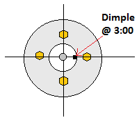
Starting from 90 ATDC on #1, pins capable of inserting, fuel pump lined up with lets say lobe #1.
rotate 90 degrees, cylinder 3 fires with lobe #2
rotate 180 degrees, cylinder 4 fires with lobe #3
Rotate 270 degrees, cylinder 2 fires with lobe #1
rotate 360 degrees, cylinder 1 fires with lobe #2
rotate 90 #2, cyl 3 fires with lobe #3
rotate 180 #2, cyl 4 fires with lobe #1
rotate 270 #2, cyl 2 fires with lobe #2
rotate 360 #2, cyl 1 fires with lobe #3 - PINS INSERT, fuel pump 240 degrees out from mark.
Rotate 90 #3, cyl 3 with lobe #1
rotate 180 #3, cyl 4 with lobe #2
rotate 270 #3, cyl 2 with lobe #3
rotate 360 #3, cyl 1 with lobe #1... Fuel pump is now exactly 180 out from starting point, pins do not insert.
Rotate 90 #4, cyl 3 with lobe #2
rotate 180 #4, cyl 4 with lobe #3
rotate 270 #4, cyl 2 with lobe #1
rotate 360 #4, cyl 1 with lobe #2 - Pins again insert, fuel pump 120 degrees out from mark.
rotate 90 #5, cyl 3 with lobe #3
rotate 180 #5, cyl 4 with lobe #1
rotate 270 #5, cyl 2 with lobe #2
rotate 360 #5, cyl 1 with lobe #3
rotate 90 #6, cyl 3 with lobe #1
rotate 180 #6, cyl 4 with lobe #2
rotate 270 #6, cyl 2 with lobe #3
rotate 360 #6, cyl 1 with lobe #1... DING DING! Back at starting point, pins insert and pump lines up.
Hopefully this helps everyone visualize how the lobes can match with the firing order, and why I think it is important to have them match with the timing mark.