It is currently Sat Oct 04, 2025 10:34 pm

All times are UTC - 5 hours [ DST ]


Post new topic Reply to topic  [ 23 posts ]  Go to page 1, 2  Next
Author Message
 Post subject: Electric fan circuit activation
PostPosted: Mon Nov 23, 2020 12:49 am 
Offline
LOST Member

Joined: Sat Apr 11, 2015 12:31 pm
Posts: 450
Location: North America
Still trying/failing to use the stock sensors/ECU to activate my cooling mods. 2005 CRD using gasser's stock electric fan lo/hi circuit & connector. Mech-fan replaced by 16" Derale two-speed puller (w/custom shroud). Two 9" pushers: one on front of AC condensor, one on Trans cooler.
Other threads advise:
- Removed/jumped relays: circuit & fan operating correctly.
- Climb local hill to get 3/4 gauge, still no fan.

So, fan circuit is activated by ECU based on signals from three sensors: Engine coolant temp, trans fluid temp, AC charge pressure [+ battery temp @pre-'05= not applicable].

I removed the AC-length serp for winter. Anybody know how to "delete" AC sensor signal to ECU? Maybe jump the contacts (2 each?) In the low & high sensor plugs?

Any other advice to get the ECU to trigger the fan circuits?

If necessary, I'll install manual switches but would prefer to get the Sensor-ECU function to auto-trigger a fan or three.
Thanks

[Also PM'd Marco re "fan-control" ECU mods within custom eco/tow/race flashes. Maybe "Winter" & "Summer" flashes removing/restoring AC sensors]

Keys- radiator cooling fan mod modification sensor problem

_________________
'15: bought '05 w/138k.
'16: HG/Rockers/ARPs/Thermo/H20pump/TbeltKit/ Seals/ Mounts/Kennedy fuel pump.
'17: bought manual Gas donor for its' ARB F/R Airlockers, OME 2.5" lift (gas-rated), JBA UCAs, ARB bumper.
'19: Trans w/Suncoast/Transgo/HDdiscs, new OME CRD-rated lift, electric tri-fan setup, BlackMagics/Centric Premiums, Airbags.


Top
 Profile  
 
 Post subject: Re: Electric fan circuit activation
PostPosted: Thu Nov 26, 2020 2:32 am 
Offline
LOST Member

Joined: Sat Apr 15, 2017 3:48 am
Posts: 462
Location: White River in the Bush South Africa
Did Your CRD originally come fitted with the CRD Electric Fan....I presume so as you have the two relays fitted in their slots inside the PDC!

If so...did that fan work OK?

If you jumper pins 30 to 87 inside the two relays you say that your Gasser fan does run? :wink:

Fuse # 16 not blown? Check that +12 volts is present on pin #86 of both relays. :wink:

Do you have continuity from ECM C1 pin #71 to High Speed Relay pin # 85(Dark Blue/Orange) and continuity from ECM C1 pin #91 to Low Speed Relay pin # 85(Dark Blue Light Green)?

Electric fan grounded properly? :?

_________________
2002 Export CRD


Top
 Profile  
 
 Post subject: Re: Electric fan circuit activation
PostPosted: Thu Nov 26, 2020 7:08 pm 
Offline
LOST Member

Joined: Sat Apr 11, 2015 12:31 pm
Posts: 450
Location: North America
- Originally mech-fan only but gasser elec-fan wiring/plug installed (apparently, the norm w/CRD's),
- Relays were there when bought in '15. Fuses must be fine because stock elec fan low/high circuits function when relay(s) removed/jumpered.
I'll explore your suggestion to:
"[Check] continuity from ECM C1 pin #71 to High Speed Relay pin # 85(Dark Blue/Orange) and continuity from ECM C1 pin #91 to Low Speed Relay pin # 85(Dark Blue Light Green)"
THAT could be the culprit: no signal at all from the ECM!
Report back.

Thanks!

_________________
'15: bought '05 w/138k.
'16: HG/Rockers/ARPs/Thermo/H20pump/TbeltKit/ Seals/ Mounts/Kennedy fuel pump.
'17: bought manual Gas donor for its' ARB F/R Airlockers, OME 2.5" lift (gas-rated), JBA UCAs, ARB bumper.
'19: Trans w/Suncoast/Transgo/HDdiscs, new OME CRD-rated lift, electric tri-fan setup, BlackMagics/Centric Premiums, Airbags.


Top
 Profile  
 
 Post subject: Re: Electric fan circuit activation
PostPosted: Fri Nov 27, 2020 7:32 pm 
Offline
LOST Member

Joined: Sat Apr 11, 2015 12:31 pm
Posts: 450
Location: North America
Couldnt find ECM pinout diagram to locate 85/91.

However, when the AC high pressure sensor plug is removed (@ AC line, by alt) the ECM activates fan-high, so that confirms that ECM-Relays are communicating.

Argh. Need this handled so looks like manual switch time.
*#@%*!!!

Or: isn't there a spot to install a 2nd temp sensor on egr side of block? If yes, seems like I could dedicate that 'surplus' sensor signal directly to the fan-low relay. I'd still have to manually activate fan-high and my two front 9's, but at least I could be brain-dead at basic elevated op temps without hazard.

EDIT: EGR coolant port is available. Anybody know a compatible temp sensor PN?
Or... anybody opine how the ECM would feel about a "Y" off of the existing temp sensor feed? Would it alter the line impedance enough to confound/P.O. the ECM?

_________________
'15: bought '05 w/138k.
'16: HG/Rockers/ARPs/Thermo/H20pump/TbeltKit/ Seals/ Mounts/Kennedy fuel pump.
'17: bought manual Gas donor for its' ARB F/R Airlockers, OME 2.5" lift (gas-rated), JBA UCAs, ARB bumper.
'19: Trans w/Suncoast/Transgo/HDdiscs, new OME CRD-rated lift, electric tri-fan setup, BlackMagics/Centric Premiums, Airbags.


Top
 Profile  
 
 Post subject: Re: Electric fan circuit activation
PostPosted: Fri Nov 27, 2020 10:26 pm 
Offline
Moderator
Moderator
User avatar

Joined: Sat Aug 24, 2013 11:36 pm
Posts: 7365
Location: Central GA
Just curious; why are you interested in pin #85 on the ECM #1 connector. (K157 20BR/OR MASS AIR FLOW 5 VOLT SUPPLY)
Don't see it having anything to do with fans circuit?
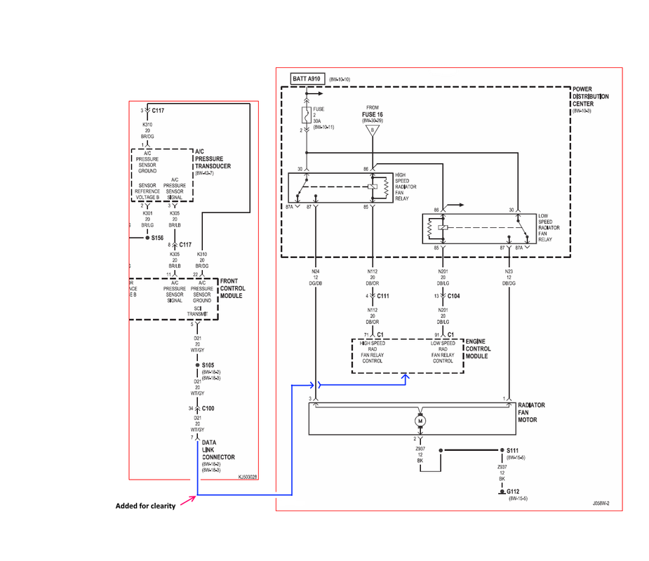
Pin #91 on ECM is low speed output ground to the low speed relay.
Pin #71 on ECM is high speed output ground to the low speed relay.

The key is the fact that the ECM is "Grounding" pins 85 on the control circuit for either the Low Speed Relay or the High Speed Relay to operate the fan in the desired speed. see wiring diagram below.
The ECM is also getting a signal from the AC transductor and exactly how that plays into the whole fan logic is still a mystery.
Without a control logic diagram for the ECM, it is all guesswork.
But if you could find a temperature thermo switch that could ground a relay at a certain desired temperature then you could wire it to one of the fan relays in place of the ECM signal on pin 85.
or
Add a complete separate control circuit using a temperature thermo switch and your own relay to operate a fan at a desired temperature.
But if you go this route, you would need to add a diode to prevent any backfeed I would think unless you totally abandon the ECM feed to the fan relay of your choosing. :wink:

Image

_________________
Supporting Vendor and Moderator of LOST
05 Jeep Liberty CRD Limited :JEEPIN:
Ironman Springs/Bilstein/Shocks
Yeti StgIV Hot Tune
Week's BatteryTray
No FCV/EGR
Samcos/ProVent
SunCoast/Transgo
Carter Intank-pmp
2mic.Sec.Fuel Filter
Flowmaster/NO CAT
V6Airbox/noVH
GM11 Bld.fan/HDClutch
IronrockArms/wwdieselMount

98 Dodge Cummins 24 Valve


Top
 Profile  
 
 Post subject: Re: Electric fan circuit activation
PostPosted: Fri Nov 27, 2020 11:42 pm 
Offline
LOST Junkie

Joined: Sat Oct 01, 2016 8:24 pm
Posts: 652
I am very interested in what you come up with, as I'm starting to think about this myself.

On my XR4TIi, I played with so many fan triggering solutions trying to get it right. I tried the probes that you stick into the radiator, an adjustable fan controller that could piggyback off the ECM's ECT sensor, sensor adapters that fit inline with the upper radiator hose, and finally ended up welding a bung into the radiator to use a common/commodity GM fan thermo-switch. No surprise, the production sensor works a lot better than all the janky aftermarket options. I built a relay system using Littelfuse parts to stage the two fans, so one comes up at a low temperature and the second when it gets warmer. In the future I want to incorporate a resistor (~0.2ohm) to create a two speed system instead of a staged one.

I love the idea of using the ECM to trigger the fan, but I'm not sure how you would know it's programmed to respond at the right temperature to do what a main fan should do. Other cars that have a similar arrangement - a main fan and a secondary AC fan - typically work by running the main fan at some low temperature (like 10-20 degrees above the thermostat temp) to do the heavy lifting, but run the secondary AC fan *either* when the AC system pressure goes up (indicating AC is on and the condenser should be cooled) OR when engine temp hits some higher threshold and "emergency cooling" is called for.

If the ECM has logic to run a main fan at a lower temp than secondary AC fan, that's awesome. It strikes me as unlikely Chrysler would have implemented that logic since it would never be used. Maybe I'm off?

FWIW, you generally don't want huge gaps between thermostat opening and fan... the goal is *generally* to keep the engine in a relatively narrow range of temperature. Big swings result in components fatiguing and economy/emissions being unstable. Especially with an iron block & alloy head where you want to keep thermal expansion to a minimum to avoid head gasket failures, etc.

If the stock thermostat is 180F, I would expect something like a ~200F fan switch to keep the engine in that 20F window. Something like that?

I was looking today at where a sensor might go but nothing struck me as great. If there is a way to use the ECM that woul be great


Top
 Profile  
 
 Post subject: Re: Electric fan circuit activation
PostPosted: Sat Nov 28, 2020 3:24 am 
Offline
LOST Member

Joined: Sat Apr 15, 2017 3:48 am
Posts: 462
Location: White River in the Bush South Africa
Some good ideas being expressed here!

ECM pinouts are on Logic Page 8W-80-68.

I agree with WWdiesel that finding a good temp. sensor to ground the relays would work fine but the correct range sensor needs to be found. :wink:

My 2002 Export 2.5 CRD which I picked up May 2002 only came with the Viscous Mechanical Fan fitted.....6 months later they came out with the addition of an electrical fan as well as disk brakes at rear and ABS which I do not have. :cry:

My Jeep works just fine but I have been toying with fitting an electric fan as an emergency backup in case the viscous clutch suddenly packs up!

I do not travel much nowadays though so I doubt that fitting an electric fan is ever going to happen. :|

_________________
2002 Export CRD


Top
 Profile  
 
 Post subject: Re: Electric fan circuit activation
PostPosted: Sat Nov 28, 2020 12:52 pm 
Offline
Moderator
Moderator
User avatar

Joined: Sat Aug 24, 2013 11:36 pm
Posts: 7365
Location: Central GA
Billybob wrote:
Some good ideas being expressed here!
ECM pinouts are on Logic Page 8W-80-68.

I agree with WWdiesel that finding a good temp. sensor to ground the relays would work fine but the correct range sensor needs to be found. :wink:
My 2002 Export 2.5 CRD which I picked up May 2002 only came with the Viscous Mechanical Fan fitted.....6 months later they came out with the addition of an electrical fan as well as disk brakes at rear and ABS which I do not have. :cry:
My Jeep works just fine but I have been toying with fitting an electric fan as an emergency backup in case the viscous clutch suddenly packs up!
I do not travel much nowadays though so I doubt that fitting an electric fan is ever going to happen. :|

FYI: Billy, that WD is for a 2006 model, his is a 2005 model. Since the 2006 does not have the Front Control Module, I am sure there are many differences.
The FSM does not show the connector pinout for the 2005, only the list table.
Says "NO CONNECTOR AVAILABLE" on page 8W-80-60. :wink:

_________________
Supporting Vendor and Moderator of LOST
05 Jeep Liberty CRD Limited :JEEPIN:
Ironman Springs/Bilstein/Shocks
Yeti StgIV Hot Tune
Week's BatteryTray
No FCV/EGR
Samcos/ProVent
SunCoast/Transgo
Carter Intank-pmp
2mic.Sec.Fuel Filter
Flowmaster/NO CAT
V6Airbox/noVH
GM11 Bld.fan/HDClutch
IronrockArms/wwdieselMount

98 Dodge Cummins 24 Valve


Top
 Profile  
 
 Post subject: Re: Electric fan circuit activation
PostPosted: Sun Nov 29, 2020 2:16 am 
Offline
LOST Member

Joined: Sat Apr 15, 2017 3:48 am
Posts: 462
Location: White River in the Bush South Africa
WWDiesel wrote:
Billybob wrote:
Some good ideas being expressed here!
ECM pinouts are on Logic Page 8W-80-68.

I agree with WWdiesel that finding a good temp. sensor to ground the relays would work fine but the correct range sensor needs to be found. :wink:
My 2002 Export 2.5 CRD which I picked up May 2002 only came with the Viscous Mechanical Fan fitted.....6 months later they came out with the addition of an electrical fan as well as disk brakes at rear and ABS which I do not have. :cry:
My Jeep works just fine but I have been toying with fitting an electric fan as an emergency backup in case the viscous clutch suddenly packs up!
I do not travel much nowadays though so I doubt that fitting an electric fan is ever going to happen. :|

FYI: Billy, that WD is for a 2006 model, his is a 2005 model. Since the 2006 does not have the Front Control Module, I am sure there are many differences.
The FSM does not show the connector pinout for the 2005, only the list table.
Says "NO CONNECTOR AVAILABLE" on page 8W-80-60. :wink:


Yeah my bad, getting old/am old :oops:

On my Export 2002 CRD I can just read the numbers on the connector using a magnifier glass and I always go by the wire colors in any case. I do not probe the connector pins themselves as it is too easy to damage them but piece the correct colored wire with a pin/needle just before the connector!

I believe the Dealers have a Plug Convertor whereby they expand the small socket to a larger one so as to be able to probe easier!

If I have to replace a wire I cut it off about an inch from the connector, solder on a new one and insulate it! Done this probably about 5 times on my ECM! :?

_________________
2002 Export CRD


Top
 Profile  
 
 Post subject: Re: Electric fan circuit activation
PostPosted: Sun Nov 29, 2020 3:07 pm 
Offline
LOST Member

Joined: Sat Apr 11, 2015 12:31 pm
Posts: 450
Location: North America
Thanks for insights!
Barring a solution to get the CRD ECM to provide the required signal to the [gasser's] elec fan relays, it seems the simplest solution would be to 'Y' the stock Coolant Temp Sensor to send a separate direct signal to the 'Fan- Low' relay.
The diode suggestion may address concerns that Y-ing into the existing CTS output wire could cause issues at the ECM.
However, the stock CTS doesn't provide an 'Off/Low/High' output signal; it sends an attenuated resistance signal for effecting the gauge. If wired directly from the stock CTS it isnt clear how the fan relay would react. As the sensor heats up and resistance decreases to the output signal (permitting more of the 5v input to pass), what voltage threshold would trigger the fan relay?
Is 5v even enough to trigger the relay?*

It seems more practical to focus on generating a completely independent (no-ECM) temp signal to the relay-block. The vacated/plugged EGR cooler port is available (engine-left). There's a 2-stage [Low/High] temp sensor for a BMW for $16; triggers @ 195 & 210f:
https://www.rockauto.com/dbphp/prt,107,61311378073
Working on the connector/pigtail and related adapter hardware.

*Bonus question: Anybody know why the ECM controls certain systems at 5v instead of 12?

_________________
'15: bought '05 w/138k.
'16: HG/Rockers/ARPs/Thermo/H20pump/TbeltKit/ Seals/ Mounts/Kennedy fuel pump.
'17: bought manual Gas donor for its' ARB F/R Airlockers, OME 2.5" lift (gas-rated), JBA UCAs, ARB bumper.
'19: Trans w/Suncoast/Transgo/HDdiscs, new OME CRD-rated lift, electric tri-fan setup, BlackMagics/Centric Premiums, Airbags.


Last edited by Gypsy62 on Sun Nov 29, 2020 5:01 pm, edited 1 time in total.

Top
 Profile  
 
 Post subject: Re: Electric fan circuit activation
PostPosted: Sun Nov 29, 2020 4:47 pm 
Offline
Moderator
Moderator
User avatar

Joined: Sat Aug 24, 2013 11:36 pm
Posts: 7365
Location: Central GA
Just a suggestion, I would stay on the ground side since the ECM simply ground switches the fan relays on or off.
If you could find a temperature "switch" as apposed to a variable resistance temperature sensor, you could very easily use it as a ground side switch for one of the OEM relays or add a whole new relay control circuit.
There are quite a few aftermarket electric cooling fan controllers that come with a temperature probe & switch that controls the fan relay. see picture below. :google:

I have a pusher fan on my Dodge gasser and it came with a temperature switch and its own relay with a probe that is inserted into the fins of the radiator.
It works very well in our hot high humidity southern environment. :wink:

https://www.amazon.com/Hayden-Automotiv ... Q93TX49976

Image

_________________
Supporting Vendor and Moderator of LOST
05 Jeep Liberty CRD Limited :JEEPIN:
Ironman Springs/Bilstein/Shocks
Yeti StgIV Hot Tune
Week's BatteryTray
No FCV/EGR
Samcos/ProVent
SunCoast/Transgo
Carter Intank-pmp
2mic.Sec.Fuel Filter
Flowmaster/NO CAT
V6Airbox/noVH
GM11 Bld.fan/HDClutch
IronrockArms/wwdieselMount

98 Dodge Cummins 24 Valve


Top
 Profile  
 
 Post subject: Re: Electric fan circuit activation
PostPosted: Sun Nov 29, 2020 5:19 pm 
Offline
LOST Member

Joined: Sat Apr 11, 2015 12:31 pm
Posts: 450
Location: North America
So your saying that the ECM closes the ground(s) to the relay(s), rather than supplying voltage? Okay; that's how my Airlift switch works, too.

Although they may well be reliable, I struggle to trust those radiator-probe setups.
I'm about to pull the trigger on the 3-pole 2-Stage CTS (for BMW) w/plug & 3-wires; about $50 delivered.
https://www.rmeuropean.com/Cart.aspx :arrow:

Anybody see a problem with the low/high fan trigger-temps located at 195/210f?

That sensor's threads are 14mm 1.5.
Anybody know the thread spec of the EGR tap @ block?
Thx

_________________
'15: bought '05 w/138k.
'16: HG/Rockers/ARPs/Thermo/H20pump/TbeltKit/ Seals/ Mounts/Kennedy fuel pump.
'17: bought manual Gas donor for its' ARB F/R Airlockers, OME 2.5" lift (gas-rated), JBA UCAs, ARB bumper.
'19: Trans w/Suncoast/Transgo/HDdiscs, new OME CRD-rated lift, electric tri-fan setup, BlackMagics/Centric Premiums, Airbags.


Top
 Profile  
 
 Post subject: Re: Electric fan circuit activation
PostPosted: Sun Nov 29, 2020 10:55 pm 
Offline
Moderator
Moderator
User avatar

Joined: Sat Aug 24, 2013 11:36 pm
Posts: 7365
Location: Central GA
Gypsy62 wrote:
So your saying that the ECM closes the ground(s) to the relay(s), rather than supplying voltage? Okay; that's how my Airlift switch works, too.

Although they may well be reliable, I struggle to trust those radiator-probe setups.
I'm about to pull the trigger on the 3-pole 2-Stage CTS (for BMW) w/plug & 3-wires; about $50 delivered.
https://www.rmeuropean.com/Cart.aspx :arrow:
Anybody see a problem with the low/high fan trigger-temps located at 195/210f?
That sensor's threads are 14mm 1.5.
Anybody know the thread spec of the EGR tap @ block?
Thx

Yes, that is exactly how it functions according the wiring diagrams in the Factory Service Manual. Study the wiring diagram below.
The ECM is simply a ground side switch. The relays are hard wired with constant 12v to the service side of the relays (terminal 30) and is also hard wired to the control side of the relay (terminal 86) on both low speed and high speed relays.

The aftermarket fan controller with a temperature probe and relay that I installed on my Dodge gasser has worked flawlessly now for several years. It even has a AC clutch feed connected that turns the pusher fan on anytime the AC compressor clutch is engaged. :D

The EGR coolant outlet fitting on the CRD head,
It is a short M12 x 1.5 plug. It is https://www.dormanproducts.com/gsearch. ... rd&q=65413 oil drain plug. Original Application is 2008 BMW 328i with 3.0L engine. You'll need a copper crush washer, also to seal it up.

Image

_________________
Supporting Vendor and Moderator of LOST
05 Jeep Liberty CRD Limited :JEEPIN:
Ironman Springs/Bilstein/Shocks
Yeti StgIV Hot Tune
Week's BatteryTray
No FCV/EGR
Samcos/ProVent
SunCoast/Transgo
Carter Intank-pmp
2mic.Sec.Fuel Filter
Flowmaster/NO CAT
V6Airbox/noVH
GM11 Bld.fan/HDClutch
IronrockArms/wwdieselMount

98 Dodge Cummins 24 Valve


Top
 Profile  
 
 Post subject: Re: Electric fan circuit activation
PostPosted: Mon Nov 30, 2020 1:53 pm 
Offline
LOST Junkie

Joined: Sat Oct 01, 2016 8:24 pm
Posts: 652
Don't forget that *where* you put the thermo-switch matters as temperature will vary across the system. I would want to measure coolant temp at that EGR port versus, say, the thermostat outlet to see that variance. Putting the sensor in the wrong spot can result in unwanted behavior. That's one strong reason to use a radiator probe (the strong reason against is that if your thermostat sticks partially closed, you can find the radiator getting relatively cool and the engine getting relatively hot). Nothing is easy! :D

Edit: I will also add that even though my adjustable fan controllers were awful over the long haul, they did allow me to mess with trigger temperatures so that when I finally used a fixed switch I knew exactly what switch to buy. :)

I keep leaning towards this on the CRD, because it will piggyback on the stock ECT sensor. Even though it's expensive, not having to mess with cramming some other sensor in is attractive.. and painless!

https://www.summitracing.com/parts/dak- ... gIwTfD_BwE


Top
 Profile  
 
 Post subject: Re: Electric fan circuit activation
PostPosted: Mon Nov 30, 2020 9:24 pm 
Offline
Moderator
Moderator
User avatar

Joined: Sat Aug 24, 2013 11:36 pm
Posts: 7365
Location: Central GA
Just a thought:
Jeff's HDS thermostat has some extra threaded ports on it that could be utilized for an additional temperature sensor or thermoswitch. :idea:

_________________
Supporting Vendor and Moderator of LOST
05 Jeep Liberty CRD Limited :JEEPIN:
Ironman Springs/Bilstein/Shocks
Yeti StgIV Hot Tune
Week's BatteryTray
No FCV/EGR
Samcos/ProVent
SunCoast/Transgo
Carter Intank-pmp
2mic.Sec.Fuel Filter
Flowmaster/NO CAT
V6Airbox/noVH
GM11 Bld.fan/HDClutch
IronrockArms/wwdieselMount

98 Dodge Cummins 24 Valve


Top
 Profile  
 
 Post subject: Re: Electric fan circuit activation
PostPosted: Mon Nov 30, 2020 11:06 pm 
Offline
LOST Junkie

Joined: Sat Oct 01, 2016 8:24 pm
Posts: 652
Yeah, I looked real hard at that, but I just couldn't make the math work.


Top
 Profile  
 
 Post subject: Re: Electric fan circuit activation
PostPosted: Tue Dec 01, 2020 3:12 pm 
Offline
LOST Member

Joined: Sat Apr 11, 2015 12:31 pm
Posts: 450
Location: North America
That summit controller is cool, thx. May be a future time & place.
Pulled trigger on 325i sensor setup yesterday (during annual consumer sharknado).

Thanks very much for the thread-spec on EGR coolant port. Yeah, after reflection I, too, realized that the EGR's port temps likely didn't jibe with the thermo's port temp-spec. My turbo water-cooling mods provide a rubber-hose to the heater core which should be temp-adequate for a sensor-install T.

Parts here in a week. Now, the question is: what's the best combo of sensor low/high w combo of 2-speed 16" Derale puller and (2) 9" pushers (one on AC condensor, one on aftermarket trans cooler).

Current plan, open to suggestions:
- Sensor's "low" replaces ECM's "low" relay-feed, dedicated solely to 16" "low" @ stock gasser plug,
- Sensor's "high" Y's into ECM's "high" relay-feed, supplying both the 16's "high" circuit as well as the 9" on AC condensor: in theory, preserving the ECM's AC pressure-sensor fan switch circuit [summer-serp install],
- Remaining 9" on trans cooler independent on manual switch (already installed). In future, maybe governed by trans fluid sensor.

Will need to test whether the dual position 325i sensor 'connects-current' or 'closes-ground' and insert into relay-feeds accordingly.
Insights welcome.

_________________
'15: bought '05 w/138k.
'16: HG/Rockers/ARPs/Thermo/H20pump/TbeltKit/ Seals/ Mounts/Kennedy fuel pump.
'17: bought manual Gas donor for its' ARB F/R Airlockers, OME 2.5" lift (gas-rated), JBA UCAs, ARB bumper.
'19: Trans w/Suncoast/Transgo/HDdiscs, new OME CRD-rated lift, electric tri-fan setup, BlackMagics/Centric Premiums, Airbags.


Top
 Profile  
 
 Post subject: Re: Electric fan circuit activation
PostPosted: Tue Dec 01, 2020 6:40 pm 
Offline
LOST Junkie

Joined: Sat Oct 01, 2016 8:24 pm
Posts: 652
I wonder if you even need the pusher fan anymore.... I'm sure it's only there to help the AC out. I would be inclined to simply wire the trigger for the pusher into the low speed on the new puller (use a diode...) and call it good. I think generally speaking there really is such a thing as "too much fan" and you just disrupt airflow. I'd at least try it this way, and revert back if you find AC performance suffered.

"Connects current" or "closes ground" are just a matter of how you wire it.... It's a three terminal switch, so "terminal 1" is connected to nothing or "terminal 2," or "terminal 3" depending on temperature. How it behaves depends on where "terminal 1" goes. IMO, "terminal 1' should go to a ground point, and "terminal 2" and "terminal 3" go to #85 on the low and high speed fan relays, respectively.

Have you found an inline fitting with an M14 thread? Or will you just get a standard 1/4" NPT fitting and retap it? M14 is a big thread to go into anything smaller than a 19mm or maybe 25mm hose. How big is the heater core hose?


Top
 Profile  
 
 Post subject: Re: Electric fan circuit activation
PostPosted: Tue Dec 01, 2020 10:29 pm 
Offline
LOST Member

Joined: Sat Apr 11, 2015 12:31 pm
Posts: 450
Location: North America
Thanks for counsel!
Gotta' confirm, but fairly certain the coolant runs are 5/8ID 7/8OD.

Re routing, thanks for heads-up re vexing the ECM with a non-ground Y. If the 325i's temp sensor isn't designed as a 'close-ground' switch there's no reason it can't be configured as one. Thanks!

I have some surplus diodes from a previous CRD RV-toad taillight setup. Hopefully suffice(?).

Btw- finally resolved the design of custom intake snorkel/filter setup. Sawed quarter-panel holes today; Yee-hah! Liberates stock airbox zone for 2nd battery install (ala diesel pickups). Also relocates my FAILED exhaust-venturi Provent-concept back to the intake path (positive-vacuum DEF required). 3" pipe (aluminized exh.) routed laterally from turbo & through 1/4 panel above right wheel flare. Only real pita is relocating the ABS-brain's fasteners. Post pics in new thread when wrapped.

_________________
'15: bought '05 w/138k.
'16: HG/Rockers/ARPs/Thermo/H20pump/TbeltKit/ Seals/ Mounts/Kennedy fuel pump.
'17: bought manual Gas donor for its' ARB F/R Airlockers, OME 2.5" lift (gas-rated), JBA UCAs, ARB bumper.
'19: Trans w/Suncoast/Transgo/HDdiscs, new OME CRD-rated lift, electric tri-fan setup, BlackMagics/Centric Premiums, Airbags.


Top
 Profile  
 
 Post subject: Re: Electric fan circuit activation
PostPosted: Wed Dec 02, 2020 12:03 am 
Offline
LOST Junkie

Joined: Sat Oct 01, 2016 8:24 pm
Posts: 652
Definitely let us know what you come up with for mounting an M14 sensor in a 5/8"/16mm hose. It's not a fitting or adapter I have seen, and you can never have too many options for mounting sensors! ;)


Top
 Profile  
 
Display posts from previous:  Sort by  
Post new topic Reply to topic  [ 23 posts ]  Go to page 1, 2  Next

All times are UTC - 5 hours [ DST ]


Who is online

Users browsing this forum: No registered users and 42 guests


You cannot post new topics in this forum
You cannot reply to topics in this forum
You cannot edit your posts in this forum
You cannot delete your posts in this forum

Search for:
Jump to:  
Powered by phpBB © 2000, 2002, 2005, 2007 phpBB Group. Color scheme by ColorizeIt!
Logo by pixeldecals.com